Question
Question: In the given circuit resistances are $R_1=6\Omega$, $R_2=4\Omega$ and $R_3=4\Omega$. Inductance is o...
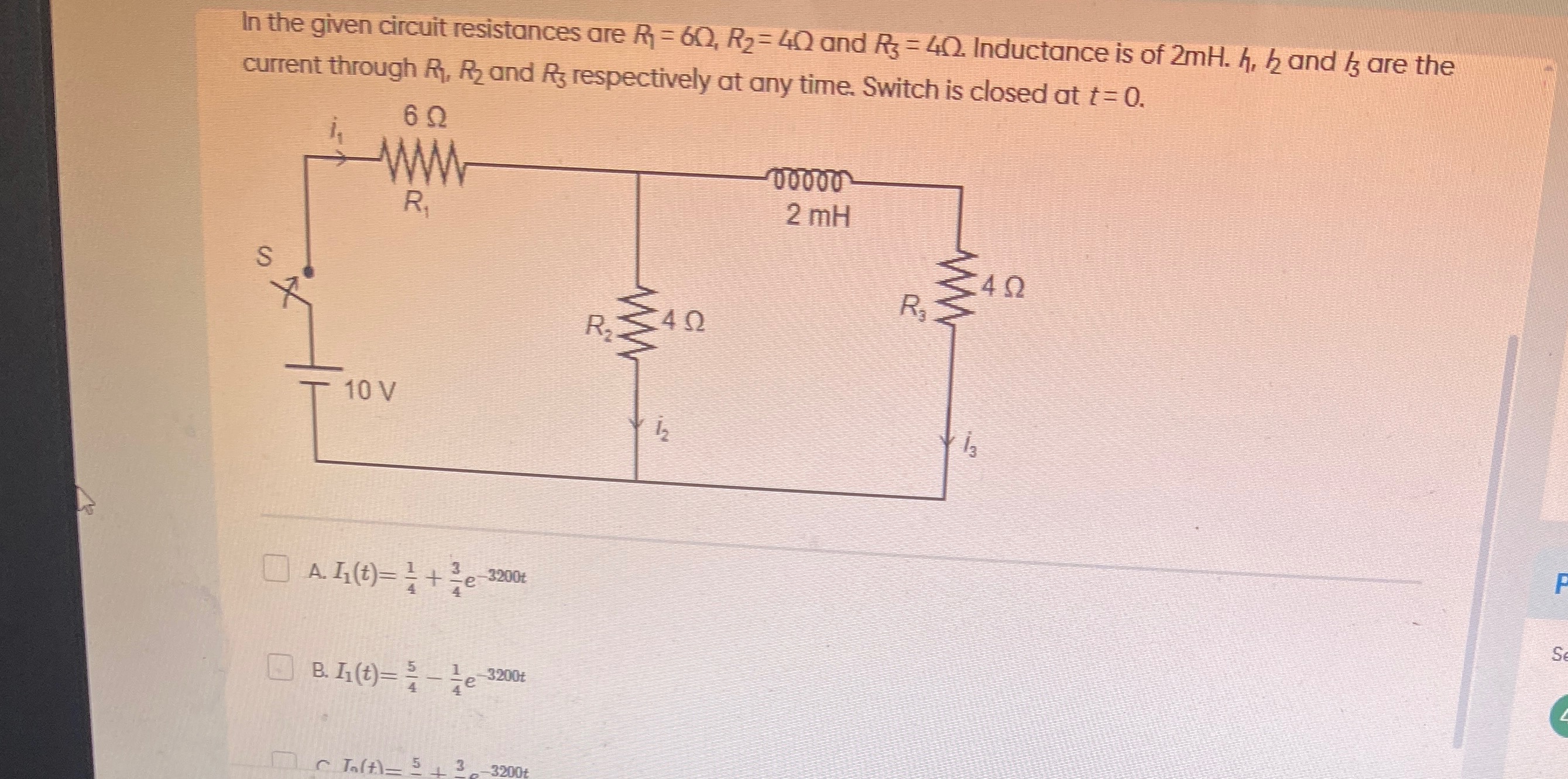
In the given circuit resistances are R1=6Ω, R2=4Ω and R3=4Ω. Inductance is of 2mH. i1, i2 and i3 are the current through R1, R2 and R3 respectively at any time. Switch is closed at t=0.
I1(t)=41+43e−3200t
I1(t)=45−41e−3200t
I2(t)=45+43e−3200t
B
Solution
To find the current I1(t) after the switch is closed at t=0, we follow the standard procedure for analyzing RL transient circuits.
1. Initial Conditions (t=0+):
At t=0+, an inductor acts as an open circuit to sudden changes in current. Since the switch is closed at t=0 and there was no current flowing before, the initial current through the inductor L (which is i3) must be zero:
i3(0+)=0.
At this instant, the path through L and R3 is effectively an open circuit. Therefore, the current i1 flows through R1 and R2 only.
The equivalent resistance at t=0+ is Req(0+)=R1+R2=6Ω+4Ω=10Ω.
The current I1(0+) is given by Ohm's Law: I1(0+)=V/Req(0+)=10V/10Ω=1A.
2. Final Conditions (t=∞, Steady State):
At steady state, the inductor acts as a short circuit.
The circuit becomes R1 in series with the parallel combination of R2 and R3.
The equivalent resistance of R2 and R3 in parallel is:
R23=R2+R3R2×R3=4Ω+4Ω4Ω×4Ω=816Ω=2Ω.
The total equivalent resistance at t=∞ is Req(∞)=R1+R23=6Ω+2Ω=8Ω.
The current I1(∞) is given by Ohm's Law: I1(∞)=V/Req(∞)=10V/8Ω=5/4A=1.25A.
3. Time Constant (τ):
The time constant for an RL circuit is τ=L/Rth, where Rth is the Thevenin equivalent resistance seen by the inductor.
To find Rth, we turn off the independent voltage source (replace it with a short circuit) and look into the terminals where the inductor is connected.
If the 10V source is shorted, R1 and R2 are in parallel. This parallel combination is then in series with R3 (from the perspective of the inductor).
R1∣∣2=R1+R2R1×R2=6Ω+4Ω6Ω×4Ω=1024Ω=2.4Ω.
Rth=R1∣∣2+R3=2.4Ω+4Ω=6.4Ω.
Now, calculate the time constant:
τ=RthL=6.4Ω2 mH=6.4Ω2×10⁻³ H=6.40.002 s=32001 s.
So, the exponential term will be e−t/τ=e−3200t.
4. General Expression for Inductor Current i3(t):
The current through the inductor follows the general form: iL(t)=iL(∞)+(iL(0+)−iL(∞))e−t/τ.
First, calculate i3(∞). At steady state, I1(∞)=5/4A. This current splits between R2 and R3.
Using the current divider rule:
i3(∞)=I1(∞)×R2+R3R2=45A×4Ω+4Ω4Ω=45A×84=45A×21=85A.
Now, substitute the values into the general form for i3(t):
i3(t)=85+(0−85)e−3200t=85(1−e−3200t).
5. Expression for I1(t):
We need to find I1(t). From Kirchhoff's Voltage Law (KVL) in the main loop containing the source, R1, and R2:
V=I1R1+I2R2.
From Kirchhoff's Current Law (KCL) at the node connecting R1, R2, and L:
I1=I2+I3⟹I2=I1−I3.
Substitute I2 into the KVL equation:
V=I1R1+(I1−I3)R2.
V=I1(R1+R2)−I3R2.
10=I1(6Ω+4Ω)−I3(4Ω).
10=10I1−4I3.
Solving for I1:
10I1=10+4I3.
I1=1+0.4I3.
Now, substitute the expression for i3(t):
I1(t)=1+0.4(85(1−e−3200t)).
I1(t)=1+104×85(1−e−3200t).
I1(t)=1+52×85(1−e−3200t).
I1(t)=1+4010(1−e−3200t).
I1(t)=1+41(1−e−3200t).
I1(t)=1+41−41e−3200t.
I1(t)=45−41e−3200t.
This matches option B.