Question
Question: In the given circuit find the current through the Zener diode. 
(A) 2.5 mA
(B) 3.3 mA
(C) 5.5 mA
(D) 6.7 mA
Solution
Draw the circuit and show the current in the circuit and apply Kirchhoff’s current law in the circuit. According to Kirchhoff’s current law, the algebraic sum of the currents flowing through a junction is zero. After applying Kirchhoff’s law we found that the current in the Zener diode is the difference of current passing through both resistors.
Complete step by step answer:
Given:
The voltage of the circuit is V1=15V.
The voltage of the zener diode is V2=10V.
The value of first resistance is R1=500Ω.
The value of second resistance is R2=1500Ω.
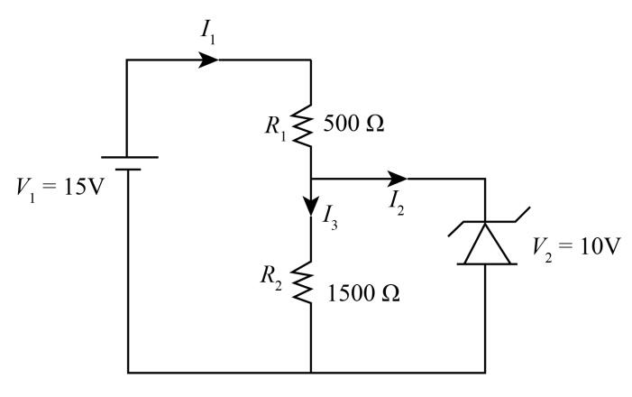
Apply Kirchhoff’s current law in the above circuit
I1−I2−I3=0 .......................(1)
The expression to calculate I2 is
I2=R2V2 ......................(2)
Substituting 10V for V2, and 1500Ω for R2 in (2), to find the value of I2.
⇒I2=1500Ω10V
⇒I2=1501A.....................(3)
The expression to calculate I1 is:
⇒I1=R1V1−V2 ................(4)
Substituting, 10V for V2, 15V for V1 and 500Ω for R1 in (4), to find the value of I1.
⇒I1=500Ω15V - 10V
⇒I1=1001A................... (5)
From equation (1), (3) and (5)
⇒(1001A)−(1501A) - (I3)=0 ⇒I3=3001A ⇒I3=0.003A×1A1000mA ⇒I3=3.3mA
As shown in diagram I3 the current passes through Zener diodes. So, the current passes through the Zener diode is 3.3mA.
Additional Information:
In a Zener diode, current flows in reverse as well as forward direction when the voltage exceeds break down voltage. This breakdown voltage is known as Zener voltage. Zener diodes are widely used as voltage regulators. Zener diode is also used to limit the current through the diode and drop the excess voltage in the conducting diode.
Note:
Zener diode is the special diode which works in reverse biased and breakdown regions. Zener diodes are used as voltage regulators. When a Zener diode is connected in forward bias then its characteristics are just the same as ordinary diodes.