Question
Question: In the given circuit diagram, the cell and the ammeter have negligible resistances. The resistances ...
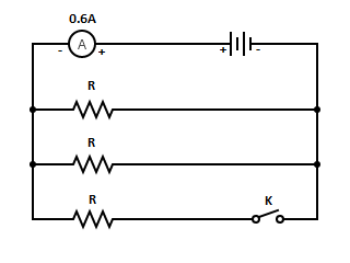
In the given circuit diagram, the cell and the ammeter have negligible resistances. The resistances are identical. With the switch K open the ammeter reads 0.6 A. What will be the ammeter reading when the switch is closed?
Solution
When the resistances are connected in parallel the total equivalent resistance is calculated by taking the reciprocal of each. Ohm's law gives the relation between the voltage, current and resistance. In an electric circuit the start of the point from where the electrons start flowing is called the source whereas the point where electrons leave the electrical circuit is called the return.
Complete step by step answer:
Let us consider the case when the switch K is open. Then, only two resistances are in circuit. These two resistances are in parallel connection. So the equivalent resistance in this case where the switch K is open can be calculated as,
R11=R1+R1 ⇒R11=R2 ⇒R1=2R
Now we can consider the potential difference of the cell. Let v volt be the potential difference. The current through the circuit is given as 0.6 A. We have the Ohm’s law that states voltage as the product of current passing through the circuit and the resistance offered by it. So, we have in this case, the voltage as,
V=IR1
Substituting the value of current and resistance in the above equation, we have,
V=0.6×2R ⇒V=0.3R
Now let us consider the case when the key is closed. When the switch K is closed all the three resistances are in parallel. So the equivalent resistance in this case where the switch K is closed can be calculated as,
R21=R1+R1+R1 ⇒R21=R3 ⇒R2=3R
Thus, again using the Ohm’s law, we can calculate the voltage as,
V=IR2
But we know that the value of V is 0.3 R and the resistance R2 as R/3. Therefore substituting these values in the above equation, we have,
0.3R=I(3R) ⇒I=R0.3R×3 ∴I=0.9A
Therefore the ammeter reads 0.9 A when the switch is closed.
Note: When the switch is open, there is no current that flows through the last section as it remains disconnected. Hence the last resistance was neglected for calculating the equivalent resistance.The electric circuits are closed-loop or path which forms a network of electrical components, where electrons are able to flow. This path is made using electrical wires and is powered by a source, like a battery.