Question
Question: In the given circuit, at time \(t = 0\), switch \({S_1}\)is closed. When a steady state is reached, ...
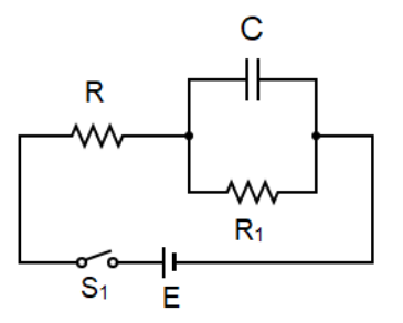
In the given circuit, at time t=0, switch S1is closed. When a steady state is reached, the switch S1 is again opened. Find the current through the resistance R1 at the instant when the switch S1is opened?
A. RE
B. R1E
C. R+R1E
D. (R+R1)R1ER
Solution
Current flows through a circuit only when a closed path is provided to it, that is, when the switch is closed. By the property of current it, gets split up at the junction but no current passes through the capacitor and hence the net resistance of the circuit will be in accordance to the resistor in series formula. The total current will be given by the formula of ohm’s law which will be the current at the instant when the switch is opened.
Formula used:
The ohm’s law is given by:
E=I×R
Where, E is the total voltage drop in the circuit, I is the current and R is the resistance.
Complete step by step answer:
When the switch is open no current flows through it because it is an open circuit and current can only flow through a closed circuit. A potential difference is generated once the switch is closed and a path is provided for the flow of charges. This potential difference is seen across the resistors in the circuit. Let’s say that this voltage that is generated is denoted by E.
The current that starts to flow once the switch is closed is given to be flowing in a steady manner. In-order to find this current we need to first look at the formula given by ohm’s law. The equation we get after rearranging the terms is:
I=RtotalE -----(1)
To find the current we need to first find out the total resistance offered by the circuit.From the diagram given we see a junction which splits to connect two elements; one path includes the capacitor and one path which includes a resistor R1 .This current at the junction can be calculated by Kirchhoff's circuit law.
Kirchhoff's first law or the junction law states that in an electric circuit the algebraic sum of currents entering a junction is equivalent to the amount of current leaving that junction. Hence, by applying this concept we can say that the current at the junctions splits to flow through the path with the capacitor and the path with the resistor.
However no current passes through the capacitor and therefore only the path with the resistor R1 is considered. This is because a capacitor has a property to block the current flowing through it if a dc voltage is connected to it which is the case here. The insulating layer between the plates of the capacitor restricts the flow of current. Hence the reactance (resistance offered by the capacitor) of the capacitor will not be taken into consideration.
Now, since the two resistances R and R1 are connected in series with each other the formula for the resistances in series is applied which says that if a number of resistances are connected in series then their equivalent that is the net resistance will be the sum of the individual resistances. Hence the formula is as follows:
Rs=R1+R2+R3+......+Rn
Since there are only two resistances:
⇒Rtotal=R+R1 -----(2)
Hence by substituting equation (2) into equation (1) we get the total current to be:
∴I=R+R1E
Hence the total current at the instant when the switch S1is opened is R+R1E .
Therefore the correct answer is option C.
Additional information: Even though ohm’s law is a useful concept in the circuitry based problems of physics it cannot be applied everywhere. There are certain limitations of ohm’s law, certain conditions where this law fails. The conductors which do not obey the ohm’s law are called non-ohmic conductors and the resistance of these conductors are said to be unstable even at a given temperature. When large amounts of current pass through metallic conductors they get heated up increasing the resistance and the graph becomes a non-linear one disobeying ohm’s law. Some other examples are the p-n junction diode, water voltameter and thyristors.
Note: A common mistake in this problem is that the current through the capacitor is also taken into consideration and the circuit given in the diagram is treated like an R-C circuit and in-order to find the total resistance of the circuit the reactance of the capacitor is found out which is wrong. The capacitor blocks the dc current as the make of the capacitor is the reason for this.