Question
Question: In the given A.C. circuit, choose the incorrect statement: 
A) Impedance of the circuit is 2Ω
B) power factor of the circuit is 1/2
C) Peak value of current through resistance is 502A
D) Average power supplied by the source is 2500W
Solution
In this solution, we will use the principles of an LCR circuit under an AC power supply. The impudence of an inductor leads to the resistor’s resistance which in turn leads to the impedance of a capacitor.
Formula used: In this solution, we will use the following formula:
- Impedance of a series LCR circuit: z=R+j(XL−XC) where R is the resistance, XL is the inductive impedance and XC is the capacitive inductance and j=−1
- Magnitude of Impedance of a series LCR circuit: ∣z∣=R2+(XL2−XC2)2 where R is the resistance, XL is the inductive impedance, and XC is the capacitive inductance.
Complete step by step answer:
In the given, A.C. circuit, we will check all the options one by one.
To calculate the impedance, we will calculate the impedance of the top branch (containing the resistor and the inductor) and that of the bottom branch (containing the capacitor).
The impedance of the top branch will be
Z1=R+jXL
⇒Z1=1+1j
where j=−1. Similarly, the impedance of the bottom branch will be
Z2=0−jXC
⇒Z2=−2j
We want to find the impedance of the circuit in option (A). To do so, we first need to find the phase angle of the top branch with the potential provided by the battery. The angle formed by the top branch will be
ϕ=tan−1(RXL)
Which gives us
ϕ=tan−1(11)
⇒ϕ=45∘
And its magnitude will be ∣Z1∣=R2+XL2
⇒∣Z1∣=12+12
Which gives us
∣Z1∣=2
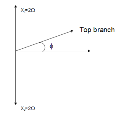
So, the top branch will be leading in phase by 45∘ with the battery potential. The bottom branch only has a capacitor so it will be lagging in phase from the potential by 90∘. So, the net angle between the top branch and the bottom branch will be 90+45=135∘. So, the net impedance can then be calculated as
Z=Z12+Z22+2Z1Z2cos135∘
Z=22+22+22(2)(2−1)
The net magnitude of the impedance of the circuit will be
Z=2+4−4
⇒Z=2
Hence option (A) is incorrect.
Note: The power factor is the cosine of the angle formed by the current in the circuit with the net impedance. So,
cosθ=ZR=21 which is the power factor.
To calculate the average power supplied and the peak current, we have to use the principles of RMS current.
So, iRMS=VRMS/Z1
⇒iRMS=2100/2=50A
Hence the peak current will be
ipeak=2iRMS=502A