Question
Question: In the following circuit, the output Y for all possible inputs A and B is expressed by the truth tab...
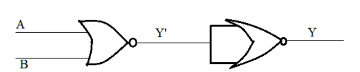
In the following circuit, the output Y for all possible inputs A and B is expressed by the truth table
(A).
A B Y
0 1 1
0 1 1
1 0 1
1 1 0
(B).
A B Y
0 0 1
0 1 0
1 0 0
1 1 0
(C).
A B Y
0 0 0
0 1 1
1 0 1
1 1 1
(D).
A B Y
0 0 1
0 1 0
1 0 0
1 1 1
Solution
Hint: Using NAND and NOR gates, we can generate all the three basic logic gates. The basic logic gates are OR, AND and NOT gates. And most importantly, we can relate the outputs of NAND gate with the output of OR gate and similarly, the output of NOR gate can be related to that for AND gate.
Complete step by step answer:
In order to answer the above question, we need to have a very clear idea about what a logic gate is and what are its different types. So, in the beginning, let us have a brief discussion about logic gates.
Definition - A gate is a digital circuit that is designed for performing a particular logical operation. As it works according to some logical relationship between input and output voltages, it is generally known as a logic gate.
Important- A logic gate may have one or more input terminals, but only one output terminal.
Classification:
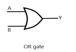
OR gate: The Boolean expression for OR gate is
Y=A+B,
where A and B are the inputs and Y is the output.
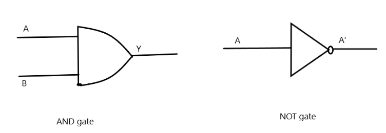
AND gate: The Boolean expression for OR gate is
Y=A.B ,
where A and B are the inputs and Y is the output.
NOT gate: The NOT gate is different from the other two gates for the reason that OR and AND gates may have two or more inputs, but will have only one output, but a NOT gate always has one input and one output. The Boolean expression for NOT gate is
A=A′ A=A′,
where A is the input and is the output
The truth table for the above mentioned gates are as under,
OR
| A | B | Y |
|---|---|---|
| 0 | 0 | 0 |
| 0 | 1 | 1 |
| 1 | 0 | 1 |
| 1 | 1 | 1 |
AND
| A | B | Y |
|---|---|---|
| 0 | 0 | 0 |
| 0 | 1 | 0 |
| 1 | 0 | 0 |
| 1 | 1 | 1 |
NOT
| A | A’ |
|---|---|
| 0 | 1 |
| 1 | 0 |
In addition we have two more gates which are considered to be universal gates as we can generate all the three basic gates, that is, OR, AND and NOT gate from those gates.
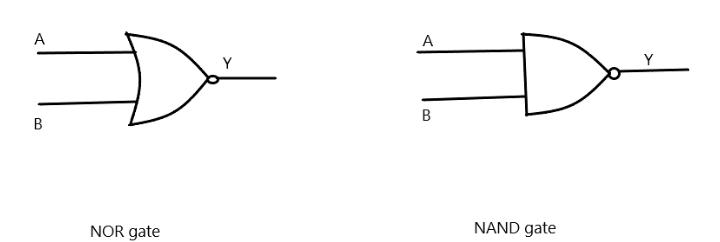
NOR gate: This logic gate is the combination of OR gate and NOT gate. The Boolean expression is,
Y=(A+B)′,
where A and B are the inputs and Y is the output.
NAND gate: This logic gate is the combination of and gate and NOT gate. The Boolean expression is,
Y=(A.B)′,
where A and B are the inputs and Y is the output.
The truth table of the gates are as under,
- NOR gate
| A | B | Y |
|---|---|---|
| 0 | 0 | 1 |
| 0 | 1 | 0 |
| 1 | 0 | 0 |
| 1 | 1 | 0 |
- NAND gate
| A | B | Y |
|---|---|---|
| 0 | 0 | 1 |
| 0 | 1 | 1 |
| 1 | 0 | 1 |
| 1 | 1 | 0 |
So, now we are in a stage to solve our question. Let us make the truth table,
| A | B | Y’ | Y |
|---|---|---|---|
| 0 | 0 | 1 | 0 |
| 0 | 1 | 0 | 1 |
| 1 | 0 | 0 | 1 |
| 1 | 1 | 0 | 1 |
Therefore, from the truth table, we get our answer as,
  option C. A B Y
                    0 0 0
                    0 1 1
                    1 0 1
                    1 1 1
Additional Information:
As the NOT gate gives the output reverse of what is given in the input, the NOT operator is known as ‘inverter’.
Note: As there is only one input and one output for a NOT gate, so there are only two columns in the case of the NOT gate. Students must also be very careful while making the truth table for the NAND and NOR gates. Many times it happens that we forget to take the compliment of the output and hence resulting in an incorrect answer, so much care should be taken while preparing the truth table of the universal logic gates.