Question
Question: In the figure there is a uniform conducting structure in which each small square has side a = 1 m. T...
In the figure there is a uniform conducting structure in which each small square has side a = 1 m. The structure is kept in uniform magnetic field B = 2 Tesla along BC.. Current of 2 amperes enters the structure at A and leaves at C. Find the correct option(s).
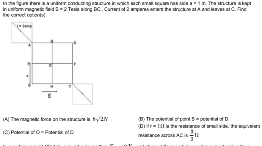
The magnetic force on the structure is 82N
The potential of point B = potential of D.
Potential of O = Potential of D
If r = 1Ω is the resistance of small side, the equivalent resistance across AC is 23Ω
B, C, D
Solution
The problem involves analyzing a uniform conducting structure in a magnetic field with current flowing through it. We need to evaluate four options related to magnetic force, potentials, and equivalent resistance.
Given:
- Side of each small square,
a = 1 m. - Magnetic field,
B = 2 Teslaalong BC. - Current,
I = 2 Aenters at A and leaves at C. - Resistance of each small side,
r = 1 Ω.
Let's set up a coordinate system with B at the origin (0,0).
Then C is at (2a, 0), E is at (0, a), A is at (0, 2a), H is at (a, 0), O is at (a, a), F is at (2a, a), G is at (a, 2a), D is at (2a, 2a).
Since a = 1 m:
A = (0, 2), C = (2, 0)
B = (0, 0), D = (2, 2)
E = (0, 1), F = (2, 1), G = (1, 2), H = (1, 0), O = (1, 1)
Option (A): The magnetic force on the structure is 82N.
For a current-carrying conductor in a uniform magnetic field, the net magnetic force is given by F=I(L×B), where L is the displacement vector from the point where current enters to the point where it leaves. Here, current enters at A and leaves at C. The displacement vector L=AC=C−A=(2−0)i^+(0−2)j^=2i^−2j^ m. The magnetic field B is along BC. Since B=(0,0) and C=(2,0), BC is along the positive x-axis. So, B=Bi^=2i^ Tesla. The current I=2 A.
Now, calculate the force: F=I(L×B) F=2 A×((2i^−2j^) m×(2i^) T) F=2×((2×2)(i^×i^)−(2×2)(j^×i^)) We know i^×i^=0 and j^×i^=−k^. F=2×(0−4(−k^)) F=2×(4k^) F=8k^ N. The magnitude of the force is ∣F∣=8 N. Therefore, option (A) is incorrect.
Option (B): The potential of point B = potential of D.
The structure is symmetric about the diagonal AC. Current enters at A and leaves at C. Points that are images of each other across the diagonal AC (the line connecting the input and output terminals) will be at the same potential. Points B and D are symmetric with respect to the diagonal AC. Therefore, VB=VD. This can also be shown by current distribution: Let IAE be the current from A to E, and IAG be the current from A to G. By symmetry, IAE=IAG=I/2. Let IEB be current from E to B, and IEO from E to O. Let IGD be current from G to D, and IGO from G to O. Due to symmetry (AE↔AG, EB↔GD, EO↔GO), IEB=IGD and IEO=IGO. Now consider potentials: VA−VE=IAEr VA−VG=IAGr Since IAE=IAG, we have VE=VG. Then, VE−VB=IEBr and VG−VD=IGDr. Since VE=VG and IEB=IGD, it implies VB=VD. Therefore, option (B) is correct.
Option (C): Potential of O = Potential of D.
From the analysis in (B), we know VB=VD. So, this option is equivalent to checking if VO=VB. Let's find the current distribution more precisely. By symmetry, the circuit can be folded along the diagonal AC. The points E and G are equipotential (VE=VG). The points B and D are equipotential (VB=VD). The points H and F are equipotential (VH=VF). Let I1 be current in AE and AG. So I1=I/2=2/2=1 A. Let I2 be current in EB and GD. Let I3 be current in EO and GO. At node E (or G): I1=I2+I3. Let I4 be current in BH and DF. Let I5 be current in OH and OF. At node B (or D): I2=I4. (Since B only connects to H). At node O: I3+I3=I5+I5⟹I5=I3. (Currents from E and G enter O, and then current leaves O via H and F). At node H (or F): I4+I5=IHC (or IFC). So, I2+I3=IHC. Total current leaving C is IHC+IFC=2(I2+I3)=I. This is consistent with I1=I/2=I2+I3.
Now let's find the potentials relative to VC=0. VH=IHCr=(I2+I3)r. VB=VH+IBHr=(I2+I3)r+I2r=(2I2+I3)r. VO=VH+IOHr=(I2+I3)r+I3r=(I2+2I3)r. For VO=VD (or VO=VB), we need (I2+2I3)r=(2I2+I3)r, which implies I2=I3. If I2=I3, then VE−VB=I2r and VE−VO=I3r. This would mean VB=VO. Let's see if I2=I3. The current I1 splits into I2 and I3 at node E. Path E-B-H-C has resistance 3r. Path E-O-H-C has resistance 2r. Since REB=r and REO=r, the currents I2 and I3 depend on the resistance of the rest of the path. The part of the circuit starting from E can be seen as: E to B (r) then B to H (r) then H to C (r). Total 3r. E to O (r) then O to H (r) then H to C (r). Total 3r. E to O (r) then O to F (r) then F to C (r). Total 3r. This is not a simple parallel combination.
Let's use the equivalent resistance calculation (from Option D). The equivalent resistance of the network across AC is Req=23r. With r=1Ω, Req=1.5Ω. Total current I=2A. VA−VC=I⋅Req=2×1.5=3 V. Let VC=0, so VA=3 V.
Let's find potentials using current values. Let IAE=IAG=I1=1 A. Let IEB=I2, IEO=I3. So I2+I3=1. Let IBH=I4, IOH=I5. At B: I2=I4. At O: I3+I3=I5+I5⟹I5=I3. At H: I4+I5=IHC. So I2+I3=IHC=1 A. VC=0. VH=IHCr=(1)(1)=1 V. VB=VH+I4r=1+I2(1)=1+I2. VO=VH+I5r=1+I3(1)=1+I3. VE=VB+I2r=(1+I2)+I2(1)=1+2I2. Also VE=VO+I3r=(1+I3)+I3(1)=1+2I3. From 1+2I2=1+2I3, we get I2=I3. Since I2+I3=1, we have 2I2=1⟹I2=0.5 A. And I3=0.5 A.
Now check potentials: VH=1 V. VB=1+I2=1+0.5=1.5 V. VD=VB=1.5 V. (Confirmed B is correct) VO=1+I3=1+0.5=1.5 V. So, VO=VD=1.5 V. Therefore, option (C) is correct.
Option (D): If r = 1Ω is the resistance of small side, the equivalent resistance across AC is 23Ω.
We can use the current distribution found above. VA=VE+I1r=(1+2I2)+I1(1)=(1+2(0.5))+1=(1+1)+1=3 V. The equivalent resistance Req=VA/I=3 V/2 A=1.5Ω=23Ω. Therefore, option (D) is correct.
Summary of correct options: Options (B), (C), and (D) are correct.
Final Answer Check: A: Force is 8N, not 82N. (Incorrect) B: VB=VD=1.5V. (Correct) C: VO=1.5V. Since VD=1.5V, VO=VD. (Correct) D: Req=1.5Ω=23Ω. (Correct)
The final answer is B, C, D.
Explanation of the solution:
- Magnetic Force (A): The magnetic force on the entire structure in a uniform magnetic field is calculated using the effective length vector from the entry point (A) to the exit point (C). L=AC=(2ai^−2aj^). Given a=1m, L=(2i^−2j^)m. The magnetic field is B=2i^ T. The force F=I(L×B)=2((2i^−2j^)×2i^)=2(4(i^×i^)−4(j^×i^))=2(0−4(−k^))=8k^ N. The magnitude is 8 N. So (A) is incorrect.
- Potential Symmetry (B, C): Due to the geometric symmetry of the structure and the current entry/exit points (A and C) being diagonally opposite corners, the network is symmetric about the diagonal AC. Points that are mirror images across the diagonal AC have the same potential. Points B and D are symmetric about AC, hence VB=VD. This confirms (B). For (C), we determined the current distribution using symmetry. Let IAE=IAG=I1, IEB=IGD=I2, IEO=IGO=I3. Also, I1=I2+I3. By applying Kirchhoff's voltage law and current law, or by observing potential drops, we found that I2=I3=0.5 A (since I1=1 A). With VC=0 and r=1Ω: VH=IHCr=(I2+I3)r=(0.5+0.5)×1=1 V. VB=VH+IBHr=VH+I2r=1+0.5×1=1.5 V. VD=VB=1.5 V. VO=VH+IOHr=VH+I3r=1+0.5×1=1.5 V. Since VO=1.5 V and VD=1.5 V, VO=VD. This confirms (C).
- Equivalent Resistance (D): The potential at A is VA=VE+IAEr=(VO+IEOr)+I1r=(1.5+0.5×1)+1×1=2+1=3 V. The total current I=2 A. The equivalent resistance Req=VA/I=3 V/2 A=1.5Ω=23Ω. This confirms (D).
The final answer is B, C, D.