Question
Question: In the figure shown, \(R=100\Omega \), \(L=\dfrac{2}{\pi }H\) and \(C=\dfrac{8}{\pi }\mu F\) are con...
In the figure shown, R=100Ω, L=π2H and C=π8μF are connected in series with an ac source of 200V and frequency f. V1 and V2 are two hot wire voltmeters. If the readings of V1 and V2 are same, then,
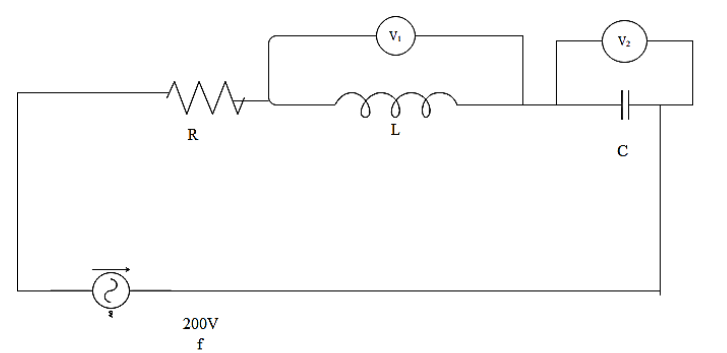
A.f=125HzB.f=250HzC.current through R is 2AD.V1=V2=1000V
Solution
Hint The voltage across the inductor and capacitors are the same. Therefore the circuit will be in resonance. Frequency of the source can be found by taking the reciprocal of the product of the constant 2π and the square root of the product of the value of the inductance and capacitance. Current through the circuit can be found using the ratio of the voltage of the source to the impedance of the circuit. These all may help you to solve this question.
Complete answer:
As it is mentioned in the question that the voltage across the inductor and the capacitor are equal, we can write that,
V1=V2
The voltage across the capacitor can be found by the equation,
V2=IXC
Where I be the current and XCbe the capacitive reactance.
The voltage across the inductor will be written as,
V1=IXL
Where XLbe the inductive reactance.
As the voltages are equal we can write that,