Question
Question: In the figure shown, if the slabs are removed and a substance of dielectric constant \(k\) is filled...
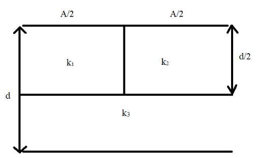
In the figure shown, if the slabs are removed and a substance of dielectric constant k is filled such that the capacitance remains the same then k is given by
A. k1=k11+k21+2k31
B. k1=k1+k21+2k31
C. k=k1+k2k1k2+2k3
D. k2+k3k2k3=k1+k3k1k3
Solution
A capacitor is a device that stores large amounts of charge which is retained within the plates of the capacitor in the form of energy. The relation between dielectric constant and capacitance must be obtained. The formula for capacitance when there is a dielectric inserted is applied and the equivalent value of capacitance needs to be determined in order to determine the equation for the dielectric constant.
Complete step by step answer:
The problem revolves around the concept of capacitors and their effect when a dielectric slab is inserted into them. In order to find the equation for the dielectric constant of the capacitors connected together we first need to know about capacitors and what a dielectric slab is. The capacitance of a capacitor is defined as the charge required to be supplied to either of the conductor plates of the capacitors in-order to increase the potential difference between them by a unit amount.
The electrical capacitance is the measure of its ability to store energy. The factors on which a parallel plate capacitor is dependent on is the area of the plates, the permittivity of the medium and the distance between the plates.Thus the capacitance of a parallel plate capacitor when there is a uniform electric field set-up between the plates of the capacitor is given by an equation:
C0=dAε0 -------(1)
Where, C0 stands for original capacitance before the dielectric slab is inserted.
A dielectric is an insulator, that is, it does not allow the flow of charges but permits the charges to exert electrostatic forces on one another through it. When this dielectric material is placed in between the plates of the capacitor it is said to be placed in an electric field that is already set up between the plates of the capacitor. The dielectric slab inserted will have a certain dielectric constant. This dielectric constant is defined as the ratio of the original field and the reduced electric field and is denoted by k.
In this problem we consider that the dielectric slabs that are inserted between the plates of each of these capacitors, fills the entire space between the plates. The effect on capacitance when the dielectric slab is inserted is measured by a factor that is said to be k. Hence the new capacitance relates the original capacitance by this equation:
C=C0k -------(2)
Where, C denotes the new capacitance value after the dielectric is placed.
Hence we can now substitute the equation (1) in equation (2) to get:
C=k×(dAε0)
⇒C=dkAε0 --------(3)
As we can see in the diagram there are three dielectric constants that are given and hence there are three capacitors that are connected together. Hence we first need to find the equivalent capacitance of all the three capacitors. The capacitors are connected in a manner shown roughly in the diagram below:
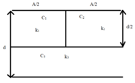
As we can see in the above diagram the capacitors C1, C2 andC3 have dielectric constants k1, k2 and k3 respectively.
From equation (3) we can determine the values of C1, C2 and C3. The area between each of the capacitor plates and the distance of separation of each of the capacitors C1 and C2 is given to be 2A and 2d respectively as given in the diagram. The area between the capacitor plates and the distance of separation of C3 is A and 2d respectively. Hence by applying the formula from equation (3) we get:
⇒C1=2dk1ε02A
⇒C2=2dk2ε02A
⇒C3=2dk3ε0A
By further simplifying these values of capacitances we get (cancelling out common terms):
⇒C1=dk1ε0A
⇒C2=dk2ε0A
⇒C3=d2k3ε0A
In-order to find out the equivalent capacitance we first need to apply the formula for the capacitance in series and capacitance in parallel. For capacitors connected in series with each other the equation is given as:
Cs1=C11+C21+....+Cn1
The equation shows that the reciprocal of the equivalent capacitance is equal to the sum of the reciprocals of the individual capacitances.
For capacitors connected in parallel with each other the equation is given as:
Cp=C1+C2+C3+....+Cn
The equation shows that the equivalent capacitance for the parallel capacitors is equal to the sum of its individual capacitances.
From the diagram we can see that the capacitors are placed horizontally on top of each other and hence we can see that C1 and C2 are connected in parallel to each other. This combination of parallel capacitors are in series to capacitor C3. We apply the parallel capacitance equation given above. Since there are two capacitors connected in parallel, that is, n=2. For capacitors C1 and C2 in parallel:
Cp=C1+C2 --------(4)
We now apply the values of C1 and C2 that we have already obtained in the above equation (4):
⇒Cp=dk1ε0A+dk2ε0A
By taking out common terms we get:
⇒Cp=dε0A(k1+k2) ---------(5)
Since this combination that is C1 and C2 are in series to C3 we now apply the series capacitance equation:
Cs1=Cp1+C31 [As per the equation for capacitors connected in series]
We now substitute equation (5) and the value for C3 in the above equation to get:
Cs1=dε0A(k1+k2)1+d2k3ε0A1
Since this is the equivalent capacitance we get:
Ceq1=dε0A(k1+k2)1+d2k3ε0A1
The common terms are taken out to get:
Ceq1=dε0A1[(k1+k2)1+2k31]
By taking the reciprocal of the above equation we get:
Ceq=dε0A×[(k1+k2)1+2k31]1
Let k denote the total value of dielectric constant given by the three capacitors. Hence:
Cp=(dε0A)k
Where,
k=[(k1+k2)1+2k31]1
Considering only this, we now take the reciprocal of this value of k to get:
∴k1=(k1+k2)1+2k31
Hence, the net dielectric constant is given by this equation.
Therefore, the correct answer is option B.
Note: A common error which can be made in the above problem is the interpreting of the diagram to identify which capacitors are connected in series and which are in parallel. The capacitors C1 and C2 are taken to be in series which is incorrect as all the capacitors are placed horizontally in the diagram so C1 and C2 are actually in parallel to each other.