Question
Question: In the figure is shown a system of four capacitors connected across a 10V battery. Charge that will ...
In the figure is shown a system of four capacitors connected across a 10V battery. Charge that will flow from switch S when it is closed is:
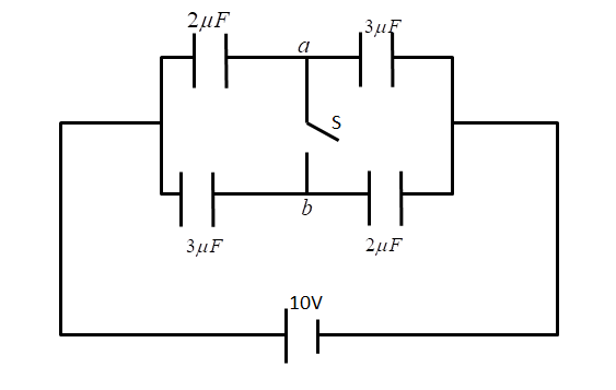
A. Zero
B. 20μC from a to b
C. 5μC from b to a
D. 5μC from a to b
Solution
Hint: To solve this problem, we will use the concept of charging and discharging of capacitors and also we know that the capacitor blocks the DC current. We will proceed by solving the series and parallel capacitor circuit for the cases when the switch is on and when the switch is closed.
Formula used- When capacitor are in series, the equivalent capacitance is
Ceq1=C11+C21 Ceq=C1+C2C1C2
And when capacitors are in parallel, the equivalent capacitance is
Ceq=C1+C2
Complete step-by-step answer:
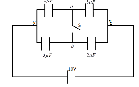
Case 1 When the switch was open, the equivalent capacitance is
For parallel path XaY
Caeq=C1+C2C1×C2 Caeq=2+32×3 Caeq=1.2μF
Similarly for the other parallel path XbY, the equivalent capacitance is
Cbeq=C3+C4C3×C4 Cbeq=2+32×3 Cbeq=1.2μF
The net equivalent capacitance is
Ceq=Caeq+Cbeq Ceq=1.2+1.2 Ceq=2.4μF
The voltage of the circuit is 10V
Net charge is given by
Qnet=CeqV Qnet=2.4μF×10V Qnet=24μC
This net charge will distribute among the capacitors as shown in the figure.