Question
Question: In the circuit shown, value of \(I\) in ampere is 
A. 1
B. 0.60
C. 0.4
D. 1.5
Solution
Hint: The given circuit has a combination of resistors both series and parallel, to find I, simplify the resistors to Rnet and use Ohm’s law.
Resistors in series: RS=R1+R2
Resistors in parallel: RP1=R11+R21
Ohm’s Law that: V=IR
Formula used:
Resistors in series: RS=R1+R2
Resistors in parallel: RP1=R11+R21
Ohm’s Law that: V=IR
Complete step-by-step answer:
To find the value of I we need to simplify the diagram. This can be done by using the resistor in series and parallel formula.
Resistors in series: RS=R1+R2 and resistors in parallel: RP1=R11+R21
We also know from Ohm’s Law that: V=IR
Using the above, since two 4Ω resistors are in parallel
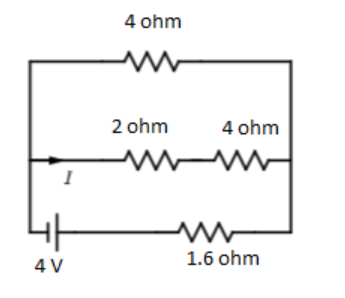
RP1=41+41=21
RP=2Ω
Again, 2Ω,4Ω resistors are in series
RS=4+2=6Ω
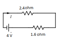
Again,4Ω,6Ω are in parallel
RP1=41+61=6×46+4=2410
RP=2.4Ω
Again, 2.4Ω,1.6Ω resistors are in series
Rnet=2.4+1.6=4Ω
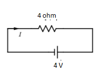
Rnet=4Ω
Since V=4V
From Ohm’s law; V=IRnet
4=I×4
I=1A
Hence the answer is A. 1
Additional Information:
Resistors are said to be in series whenever the current flows through the resistor equally. The equivalent resistance of a series resistor is equal to the algebraic sum of the individual resistances. The current in the circuit depends on the voltage supplied by the voltage source and the potential crop across the resistor. As energy is conserved, the sum of potential drop due to each resistor is equal to the voltage source.
V=V1+V2=IR1+IR2=I(R1+R2)=IRnet
I=RnetV
Rnet=R1+R2
Similarly, resistors are said to be in parallel when one end of the resistors are connected by a wire, and the other end by another wire, thus the potential drop across each resistor is the same. At the junction since different currents flow through the different resistors, the sum of the individual currents is equal to the current in the circuit.
I=I1+I2=R1V+R2V
I=V(R11+R21)=RnetV
Rnet1=R11+R21
Note: Be careful in identifying if the resistance is connected in series or parallel, and use the proper formula. While using resistors in parallel formula, don’t forget to take the reciprocals of the resistance. Also remember the principle behind the connections.