Question
Question: In the circuit shown, the capacitor is initially uncharged and the battery is ideal, if the switch i...
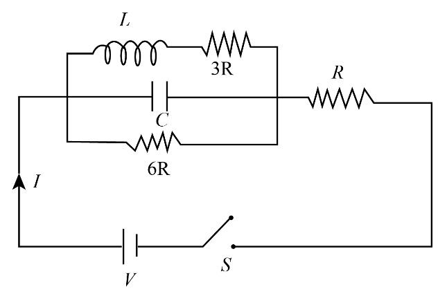
In the circuit shown, the capacitor is initially uncharged and the battery is ideal, if the switch is closed at t=0. The ratio of current through the cell at t=0 and at t=∞, will be
Solution
We will utilize the expressions for equivalent resistance when two resistors are connected in series and parallel combinations. We will also use the concept of Ohm’s law to find the value of currents at t=0 and at t=∞.
Complete step by step answer:
At the time t=0s, switch S will be closed which means the circuit is completed and the flow of current through the battery will take place. In this situation, the inductor will act as an open circuit that means it will not allow current to flow through it. The current will now flow through the capacitor of capacitance C and we know that capacitor allows the flow of current through it when is it is charging that means current flowing through the circuit is given by the ratio of voltage of the battery and resistance R as below:
I1=RV
Here I1 is the value of current when switch S is just closed.
At the time t=∞, the capacitor will be fully charged and we know that a fully charged condition capacitor does not allow the current to pass through it and the inductor allows the current to pass through it. So we will get the flow of current through the parallel combination of 3R and 6R resistor.
Using the concept of equivalent resistance of two resistors of resistances R1 and R2 when they are connected in parallel combination can be written as below:
R′=R1+R2R1R2
Here R′ is the equivalent resistance of the parallel combination of 3R and 6R resistors.
We will substitute 3R for R1 and 6R for R2 in the above expression.