Question
Question: In the circuit shown in the figure, when the input voltage of the base resistance is \(10V\), \({{V}...
In the circuit shown in the figure, when the input voltage of the base resistance is 10V, Vbe is zero and Vce is also zero. Value of β is
(A). 133
(B). 154
(C). 196
(D). 105
Solution
The figure given above shows a transistor with three parts. The current gain is the ratio of the collector current to the ratio of the base current. The emitter and collector current can be calculated by using ohm’s law. The potential can be calculated by taking the difference of potential difference between two points.
Formula used:
Vi−Vbe=IbRb
VCC−Vce=IcRc
β=IbIc
Complete step by step solution:
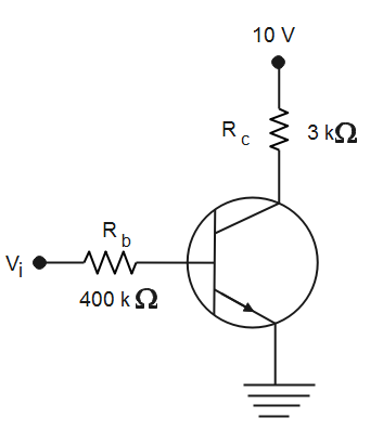
Given that, Vbe=0, Vce=0. Conditions given in the figure are Vi=10V, Rb=400×103Ω, Rc=3×10³Ω, VCC=10V.
We know that,
Vi−Vbe=IbRb
Here, Vbe is the voltage of the junction between base and emitter
According to the ohm’s law, IbRb is the potential drop across the resistor Rb.
Now we will substitute given values in the above equation to get,
10−0=Ib×400×103⇒400×10310=Ib⇒25×10−6A=25μA=Ib
Therefore, the current flowing through the resistance and between Rb is 25×10−6A.
Similarly,
VCC−Vce=IcRc
Here, Vce is the voltage between collector-emitter junction
According to ohm’s law, IcRc is the potential drop across the resistor Rc
Now we will substitute given values in the above equation to get,
10−0=Ic×3×10³⇒3×10310=Ic⇒3.33mA=Ic
Therefore the current flowing through the resistor Rc is 3.33mA.
Now,
β=IbIc
Here, β is the current gain in the transistor
Ic is the collector current
Ib is the base current
Given, Ic=3.33mA, Ib=25μA
Now we will substitute given values in the above equation to get,
β=IbIc⇒β=25×10−63.33×10−3⇒β=133
Therefore, the value of current gain in the circuit is 133. Hence, the correct option is (A).
Note: The transistor contains three parts; the emitter, collector and the base. The current gain is a unitless quantity as it is the ratio of two quantities with similar units. Current gain can be defined as the change in collector current per unit change in the base current. The above circuit is a base-configuration.