Question
Question: In the circuit shown in the figure, the input voltage \[{{\rm{V}}_{\rm{i}}}\] is 20 V, \[{{\rm{V}}_{...
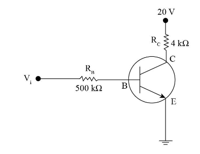
In the circuit shown in the figure, the input voltage Vi is 20 V, VBE=0 and VCE=0. The values of IB,IC and β are given by
(1) IB=20μA,IC=5mA,β=250
(2) IB=25μA,IC=5mA,β=200
(3) IB=40μA,IC=10mA,β=250
(4) IB=40μA,IC=5mA,β=125
Explanation
Solution
In the following question, the given circuit diagram is that of n-p-n bipolar junction transistor. The values for the base current, collector current and the current gain can be calculated by applying Kirchhoff’s law for each branch.
Complete step by step answer:
The input voltage is Vi = 20 V.
The voltage in BE is VBE=0.
The voltage in CE is VCE=0.
Applying Kirchhoff’s law to the lower branch of the circuit we have,
Vi=IBRB+VBE……(i)
On substituting the given values in the above equation we get,