Question
Question: In the circuit shown in the figure, the current through \({R_2}\) is zero if \({R_4} = 2\Omega \) an...
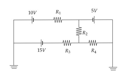
In the circuit shown in the figure, the current through R2 is zero if R4=2Ω and R3=4Ω. In this case:
A) current through R3 is 2A
B) current through R4 is 3A
C) both A and B are correct
D) both A and B are wrong
Solution
Here it is mentioned that the resistance R2 is zero. So we can redraw the given circuit diagram by replacing that resistor with a straight wire. Then we will obtain two circuits. The first circuit will comprise resistances R1 and R3 while the second circuit comprises the resistance R4 . The current through the required resistors can then be determined by applying Ohm’s law to each circuit.
Formula used:
Ohm’s law given the current in a circuit as I=RV where V is the potential difference across the circuit and R is the resistance offered by the circuit.
Complete step by step solution:
Sketch the given circuit diagram and mark the junctions involved.
It is given that R3=4Ω and R4=2Ω .
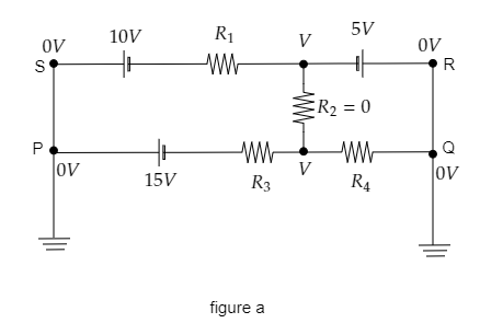
From the above figure, we see that points P and Q are connected to ground so the potential at those points will be zero. Then the potential at points S and R will also be zero. The potential difference across the resistor R2 will be V since it is given that R2=0 .
Now we can replace R2 by a straight wire so that we split the above circuit into two circuits. In the first circuit, the current will be i1 and in the second circuit, the current will be i2 . This is shown in the figure below.
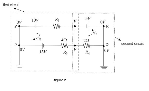
Using Ohm’s law, express the current in the second circuit.
In the second circuit, the potential difference is given by the emf of the cell i.e., V=5V .
The resistance offered by the circuit is given to be R4=2Ω.
Then by Ohm’s law, the current through the second circuit is expressed as i2=R4V=25=2.5A.
So the current through R4 will be 2.5A .
So options B and C are not correct.
Sketch the first circuit with the net EMF and the effective resistance to obtain the current through this circuit using Ohm’s law.
The two cells of emf 10V and 15V will give a net EMF of Vnet=15−10=5V .
Also the two resistors R1 and R3 give an effective resistance of Reff=R1+R3 .
This is sketched in the figure below.
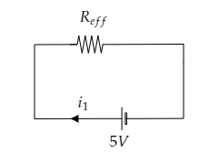
Then by Ohm’s law, the current in this circuit can be expressed as i1=ReffVnet=R1+R3Vnet ------- (1)
Now substituting for R3=4Ω , R1=0 and Vnet=5V , then we get, i1=0+45=1.25A
The current through the circuit and the current through R3 will be the same. So the current through R3 is obtained to be 1.25A .
So option A is also incorrect and thus the correct option will be D.
Note: In figure b, the resistors R1 and R3 are connected in series so we have the effective resistance of the first circuit to be the sum of the two resistances. In a series connection, the current through the two resistors will be the same. Also, the cells in the first circuit are connected in series with their positive terminal connected together, so the net EMF will be the difference between the two EMFs.