Question
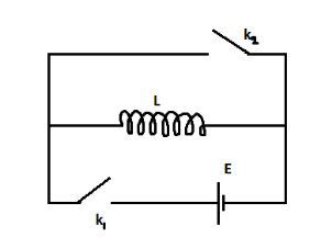
Question: In the circuit shown in the figure, switch \({k_2}\) is open and switch \({k_1}\) is opened at \(t =...
In the circuit shown in the figure, switch k2 is open and switch k1 is opened at t=0. At time t=to, switch k1 is opened and switch k2 is simultaneously closed. The variation of inductor current with time is
Solution
when switch k1 is closed an emf is induced in the circuit. Applying the formula of emf for the inductor inducing it, we will establish a relation between inductor current and time.
In the above relation, when the boundary conditions of the second circuit alignment is inputted, we will obtain another relation between current and time.
Formulae used: emf is induced in the circuit: E=Ldtdi.
Where E is the induced emf and is expressed in Volts (V), L is the inductance and is expressed in Henry (H), di is the change in current and is expressed in Ampere (A) and dt is the time taken for the current to change and is expressed in seconds (s).
Step by step solution: When k1 is closed, current flows in the circuit due to the battery connected to it. The presence of the inductance coil creates a magnetic flux, which on changing, results in the induction of an electromagnetic force. This is represented by E and is equal to Ldtdi.
Applying the boundary condition at t=0 we get,
E=Ldtdi ⇒di=LE×dt
Upon integration within the limits of 0→to we get,
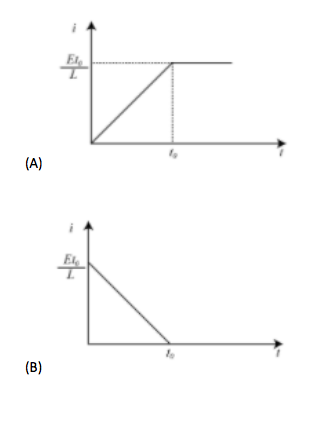
⇒∫0Itodi=∫0toLE×dt ⇒Ito=LEto
This linear variation is from t to to.
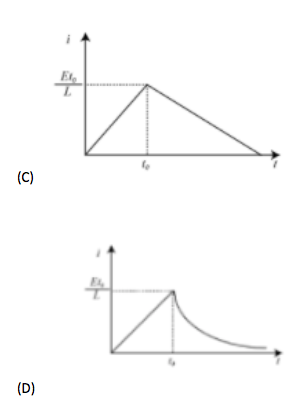
Now, applying the boundary conditions at t>to having limits of to→∞ we get,
E=Ldtdi ⇒di=LE×dt ⇒∫Ito∞di=∫∞toLE×dt ⇒I∞−Ito=LE(t∞−to)
Which is impossible.
Therefore Ldtdi=0 is considered.
This is a constant and therefore there is no variation in inductor current with time.
In conclusion, the correct graph is option A.
Note: The first boundary condition is not t=0. It ranges from t=0 to t=to. Similarly, the second one is also a range, that is, t=to to t=t∞. Calculations are made to be considered in a given time period and not just at a particular instant of time.
Additional information: A LR circuit is a circuit having a combination of inductor(s) and resistor(s). In AC circuits, they reduce voltage and in DC circuits, the inductor acts as a static resistance. Therefore, the circuit given in the above problem has DC connection because no resistor is present.