Question
Question: In the circuit shown in the figure power factor of the box is \(0.5\) and the power factor of the ci...
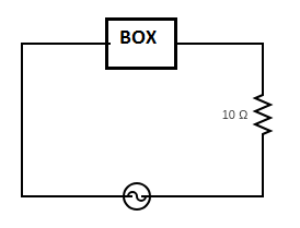
In the circuit shown in the figure power factor of the box is 0.5 and the power factor of the circuit is 23. The current is leading the voltage. Find the effective resistance (in ohms) of the box.
Solution
Capacitance opposes the change in voltage and serves to delay the increase or decrease of voltage across the capacitor. This causes the voltage to lag behind the current in a capacitive circuit. When L or C is present in an ac circuit, energy is required to build up a magnetic field around L or an electric field in C. This energy comes from the source.
Complete step by step answer:
Given, power factor of the box is given by, cosϕbox=0.5
Then, ϕbox=cos−1(0.5)
⇒ϕbox=600
Similarly, power factor of the circuit is given by, cosϕcircuit=23
Then, ϕcircuit=cos−1(23)
⇒ϕcircuit=300
Given, resistance in the circuit R=10Ω
Here we need to find the resistance to the box.
Let Rbox be the effective resistance of the box.
It is given in the question that the current is leading the voltage. From this, we can say that the given circuit is a purely capacitive circuit.
Thentanϕbox=RboxXc
Where XC is the reactive capacitance of the circuit.
We have, ϕbox=600and tan600=3 then
Above equation becomes, 3=RboxXc
⇒XC=3Rbox ………………..(1)
Similarly,
⇒tanϕcircuit=Rcircuit+RboxXc
We have, ϕbox=300and tan300=31
Then the above equation becomes,
⇒31=Rcircuit+RboxXc
⇒Xc=3Rcircuit+Rbox
We can substitute the values in the equation we get,
⇒Xc=310+Rbox ……………………(2)
Compare equation (1) and (2) we get,
⇒3Rbox=310+Rbox
Simplifying the above equation we get,
⇒3×3Rbox=10+Rbox
⇒3Rbox=10+Rbox
∴Rbox=5Ω
Therefore, the effective resistance (in ohms) of the box is 5Ω.
Note:
Consider a circuit containing an inductor, capacitor and resistor connected in series across an alternating source of voltage V or emf ε .
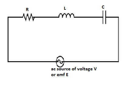
Let the source supplies a sinusoidal voltage which is given by,
V=V0sinωt
Where, V0 is the peak value of voltage ω is the angular frequency and t is the time period.
Let q be the charge on the capacitor and I be the current in the circuit at any instant of time t.
LetVR,VL,VC represent the voltage across the resistor, inductor, and capacitor respectively.
Then, voltage across resistor, VR=i0R
Voltage across inductor, VL=i0XL
Voltage across capacitor, VC=i0XC
Where, i0 is the peak value of current, XC is capacitive reactance, XL is the inductive reactance and R is the resistance of the resistor.
Then net voltage or emf is given by, V or ε=(VR2+(VL−VC)2)