Question
Question: In the circuit shown in figure, the switch 'S' is closed at t = 0. The value of current in the resis...
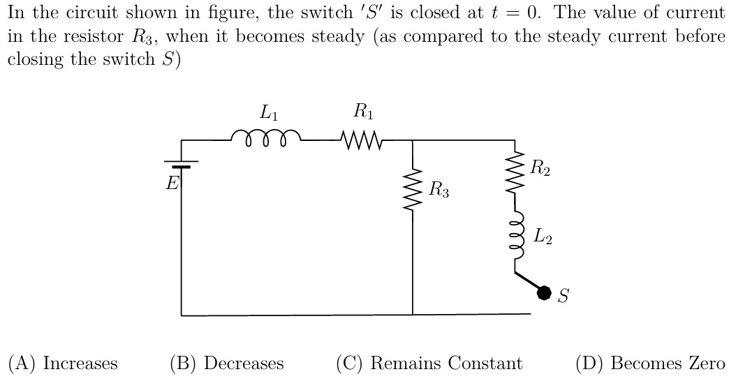
In the circuit shown in figure, the switch 'S' is closed at t = 0. The value of current in the resistor R3, when it becomes steady (as compared to the steady current before closing the switch S)
Increases
Decreases
Remains Constant
Becomes Zero
Decreases
Solution
To determine the change in current through resistor R3 when the switch 'S' is closed and the circuit reaches a steady state, we need to analyze the circuit in two steady-state conditions: before closing 'S' and after closing 'S'.
Key Concept for Steady State in RL Circuits: In a DC circuit, at steady state, inductors act as short circuits (their resistance is zero because the current is constant, so LdtdI=0).
1. Before closing switch 'S' (t < 0, steady state):
- The switch 'S' is open, so the branch containing R2, L2, and 'S' is an open circuit and carries no current.
- Inductor L1 acts as a short circuit.
- The circuit effectively consists of the voltage source E, resistor R1, and resistor R3 connected in series.
The total resistance of the circuit is: Req,before=R1+R3
The total current drawn from the source is: Itotal,before=R1+R3E
Since R1 and R3 are in series, the current through R3 is: IR3,before=Itotal,before=R1+R3E
The voltage across R3 is: VR3,before=IR3,before×R3=R1+R3ER3
2. After closing switch 'S' (t → ∞, steady state):
- The switch 'S' is closed.
- Both inductors L1 and L2 act as short circuits.
- Now, resistor R3 is in parallel with resistor R2.
The equivalent resistance of the parallel combination of R3 and R2 is: Rp=R3+R2R3R2
It's important to note that for any positive R2 and R3, the equivalent resistance of parallel resistors is always less than the smallest individual resistance. Therefore, Rp<R3.
The total equivalent resistance of the entire circuit is now: Req,after=R1+Rp=R1+R3+R2R3R2
Since Rp<R3, it implies: R1+Rp<R1+R3 So, Req,after<Req,before
The total current drawn from the source is: Itotal,after=Req,afterE
Since Req,after has decreased, the total current drawn from the source must increase: Itotal,after>Itotal,before
Now, let's find the current through R3 in this new steady state. The voltage across the parallel combination of R3 and R2 (which is also the voltage across R3) is given by: VR3,after=Itotal,after×Rp Also, by Kirchhoff's Voltage Law for the main loop: VR3,after=E−Itotal,after×R1
Since Itotal,after has increased compared to Itotal,before, the voltage drop across R1 (Itotal,after×R1) has increased. As VR3,after=E−(increased voltage drop across R1), it follows that VR3,after must be less than VR3,before.
Since the voltage across R3 has decreased (VR3,after<VR3,before), and the resistance R3 itself remains constant, the current through R3 must also decrease: IR3,after=R3VR3,after Since VR3,after<VR3,before, then IR3,after<IR3,before.
Therefore, the value of current in the resistor R3 decreases.