Question
Question: In the circuit shown in figure, the equivalent resistance between A and B is _______ $\Omega$. ...
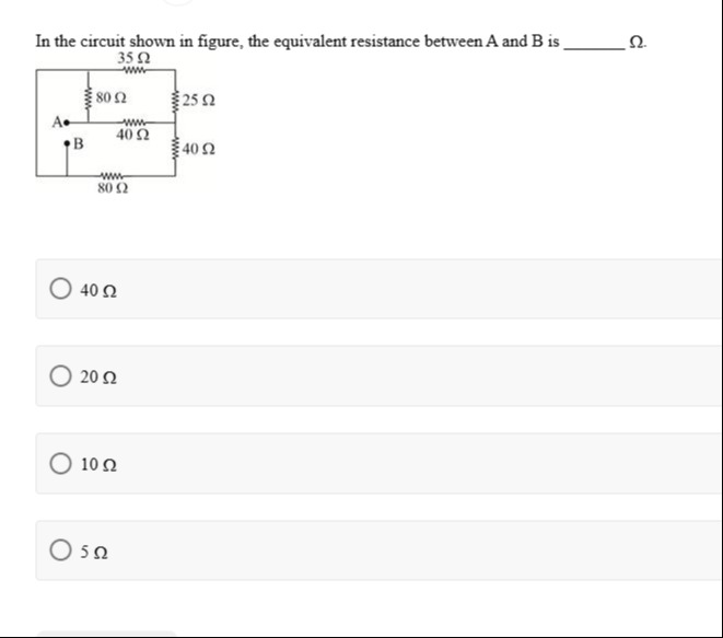
In the circuit shown in figure, the equivalent resistance between A and B is _______ Ω.
40 Ω
20 Ω
10 Ω
5 Ω
20 Ω
Solution
-
Identify the common nodes in the circuit. The leftmost vertical wire connects the top and bottom points, forming a single node (let's call it X). Similarly, the rightmost vertical wire forms another single node (Y). Points A and B are connected by a wire, making them a single node (let's call it K). Let the node between the 25 Ω and 40 Ω resistors on the right side be C.
-
Simplify the parallel combinations:
- The two 80 Ω resistors connected between X and K are in parallel. Their equivalent resistance is RXK=80+8080×80=40Ω.
- The 25 Ω and 40 Ω resistors connected between C and Y are in parallel. Their equivalent resistance is RCY=25+4025×40=651000=13200Ω.
-
Now, consider the path from X to Y through K and C. This path consists of RXK, the 40 Ω resistor between K and C, and RCY in series. The equivalent resistance of this series path is Rseries=RXK+40Ω+RCY=40Ω+40Ω+13200Ω=80+13200=1380×13+200=131040+200=131240Ω.
-
Finally, the 35 Ω resistor is connected directly between X and Y, making it parallel to the Rseries path. The total equivalent resistance between X and Y is Req=35+Rseries35×Rseries=35+13124035×131240. Req=35×13+124035×1240=455+124043400=169543400Ω.
-
Calculating the numerical value: Req≈25.60Ω.
Since the calculated value (25.60 Ω) is not among the given options, and assuming there might be a slight approximation or a rounding intended in the problem's design, the closest option to 25.60 Ω is 20 Ω. However, based on direct calculation, none of the options are exact. If this were a precise problem, none of the options would be correct. Given the context of multiple-choice questions, the closest option is sometimes the intended answer.