Question
Question: In the circuit shown in figure \[\mathop E\nolimits_1 = 7\], \[\mathop E\nolimits_2 = 7\], \[\mathop...
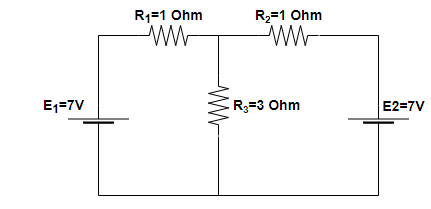
In the circuit shown in figure E1=7, E2=7, R1=R2=1Ω and R3=3Ω respectively. The current through the resistance R3 is:
(A) 2A
(B) 3.5A
(C) 1.75A
(D) None of these
Solution
The given problem can be seen as a problem based on the combination of cells. For solving these types of problems, the whole circuit is divided into different-different loops and using KVL (Kirchhoff’s Voltage Law) or KCL (Kirchhoff’s Current Law) in these loops’ measurements are done.
Complete step by step answer:
Step 1:
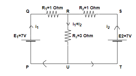
In the above figure, it can be seen that the current flowing into the circuit because of the voltage source E1 is i1 and because of the voltage sourceE2 is i2.
Using the KVL in the loop PQRUP –
E1−i1R1−(i1+i2)R3=0
Now, using the given values in the above equation
7−1×i1−(i1+i2)×3=0
Now on rearranging the equation
7−1×i1−3×i1−3×i2=0
4×i1+3×i2=7 (1)
Step 2: Similarly, using KVL in loop PQRSTUP –
E1−i1R1+i2R2−E2=0
Now using the given values in above equation
7−1×i1+1×i2−7=0; on solving this equation
i1=i2 (2)
Now substituting the values from equation (2) into equation (1), we will get –
4×i1+3×i1=7 on solving this equation
i1=i2=1A
Step 3: So, the total current flowing in the branch containing the resistance R3 is equal to the sum of the currents flowing through it because of both the voltage sources E1 and E2 i.e., i1and i2 respectively.
So, i3=i1+i2
i3=2A
∴ Hence, option (A) is correct.
Note:
(i) While solving this question, we have to take the loop PQRUP and loop PQRSTUP into consideration. If we will take loop PQRUP and loop RSTUR then these two loops will give the identical equations for KVL. So, after solving these identical equations we will have 0=0 from and not able to calculate the values for currents flowing in the circuit i.e., i1and i2 .
(ii) This problem can also be solved by the ‘Superposition Theorem’. It states that for a linear system the response (voltage or current) in any branch of a bilateral linear circuit having more than one independent source equals the algebraic sum of the response caused by each independent source.