Question
Question: In the circuit shown in figure, if no current flows through the galvanometer when the key (k) is clo...
In the circuit shown in figure, if no current flows through the galvanometer when the key (k) is closed, the bridge is balanced. The balancing condition for bridge is:

(A)C2C1=R2R1(B)C2C1=R1R2(C)C22C12=R2R1(D)C22C12=R1R2
Solution
Since, the bridging condition is achieved after the key has been closed. We will therefore work under the assumption that sufficiently long time has passed and that both the capacitors are in their steady state. Now, under steady state no current flows through a capacitor. We will use this and the fact that, since there is no current through the galvanometer, therefore its two ends will be at the same potential.
Complete answer:
Let us first assign the different points in the given figure:
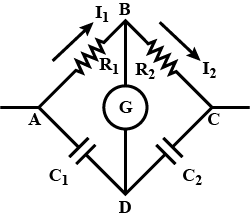
From the above figure, we can conclude that there will be no current in the branch AD and branch DC, since capacitors are in steady state.
Also, since there will be no current through the galvanometer in the bridging condition, therefore the potential at B will be equal to potential at D.
And lastly, since there is no current in the BD branch, the charge distribution on both the capacitors will be the same.
Now, we shall proceed as follows:
Let the charge on each capacitor be ‘q’.
Since, there is no current through any of the capacitors, therefore:
⇒I1=I2 [Let this expression be equation number (1)]
Also,
⇒VB=VD⇒VA−VB=VA−VD
⇒I1R1=C1q [Let this expression be equation number (2)]
Similarly, approaching both the terminals through opposite sides, we can write:
⇒VB=VD⇒VB−VC=VD−VC
⇒I2R2=C2q [Let this expression be equation number (3)]
Thus, on dividing equation number (3) by (2), we get:
⇒C1qC2q=I1R1I2R2⇒C2C1=I1R1I2R2
Therefore, on using equation number (1), we get:
∴C2C1=R1R2
Hence, the ratio for the condition of bridging comes out to be as C2C1=R1R2.
Hence, option (B) is the correct option.
Note:
We had to assume that the capacitors are in their steady states because, if not so, then the current in the whole circuit would be varying with time, as current through a capacitor decreases exponentially with time which would have made no sense in solving our problem. So, sometimes even if it isn’t mentioned in the problem we should make proper assumptions before solving the problem.