Question
Question: In the circuit shown in figure equivalent capacitance across AB is (all capacitance in µF)...
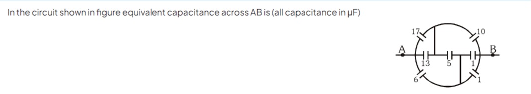
In the circuit shown in figure equivalent capacitance across AB is (all capacitance in µF)
9 µF
Solution
The circuit can be simplified by identifying the common node connecting several capacitors. Let the central vertical line represent a single node, say X. Then, capacitors 17, 6, and 13 are connected between terminal A and node X. These are in parallel, so their equivalent capacitance is 17+6+13=36μF. Capacitors 10, 1 (top), and 1 (bottom) are connected between node X and terminal B. These are in parallel, so their equivalent capacitance is 10+1+1=12μF. The capacitor 5 is connected between two points on the horizontal line that are connected to the central vertical line (node X). Thus, capacitor 5 is connected between X and X, which is a short circuit and does not contribute to the equivalent capacitance. The equivalent capacitance between A and B is the series combination of the equivalent capacitance between A and X and the equivalent capacitance between X and B.
CAB=CAX+CXBCAXCXB=36+1236×12=4836×12=436=9μF.