Question
Question: In the circuit shown in figure all resistances are identical (each equal to R) and the cell has an e...
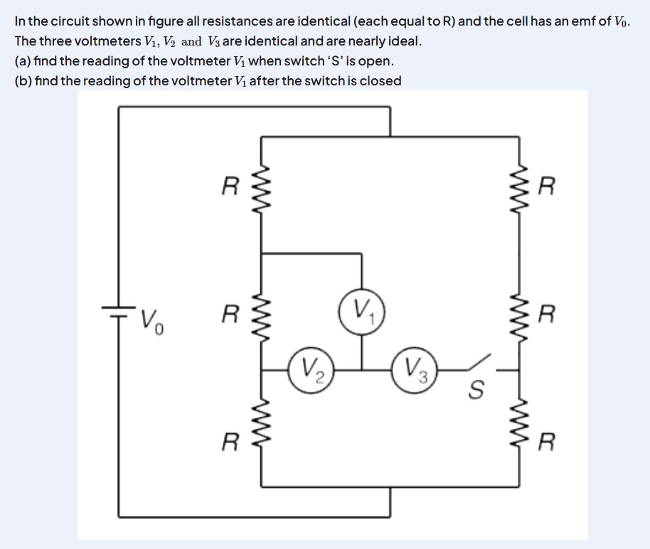
In the circuit shown in figure all resistances are identical (each equal to R) and the cell has an emf of V0. The three voltmeters V1, V2 and V3 are identical and are nearly ideal. (a) find the reading of the voltmeter V1 when switch 'S' is open. (b) find the reading of the voltmeter V1 after the switch is closed
a) V_0/6, b) 2V_0/9
Solution
The problem asks for the reading of voltmeter V1 in two scenarios: (a) when the switch 'S' is open, and (b) when the switch 'S' is closed. All resistances are identical (each equal to R), and the cell has an emf of V0. The three voltmeters V1, V2, and V3 are identical and nearly ideal. "Nearly ideal" implies that their internal resistance (RV) is very large but finite, allowing them to establish a potential at the common junction without drawing significant current from the main circuit. Therefore, the current distribution in the resistor branches remains unaffected by the voltmeters.
First, let's determine the potentials at the various nodes in the resistor network. Let the negative terminal of the battery be at 0V and the positive terminal at V0. The circuit consists of two parallel branches, each with three identical resistors (R) in series. The total resistance of each branch is Rtotal=R+R+R=3R. The current flowing through each branch is I=V0/(3R).
Let's label the nodes:
- Node N1: Between the top R and middle R on the left side.
- Node N2: Between the middle R and bottom R on the left side.
- Node N3: Between the top R and middle R on the right side.
- Node N4: Between the middle R and bottom R on the right side.
The potentials at these nodes, relative to the 0V terminal, are: VN1=V0−I×R=V0−(V0/3R)×R=V0−V0/3=2V0/3. VN2=V0−I×2R=V0−(V0/3R)×2R=V0−2V0/3=V0/3. Similarly for the right branch: VN3=2V0/3. VN4=V0/3.
Let J be the common junction point where the voltmeters V1, V2, and V3 meet.
- V1 is connected between N1 and J.
- V2 is connected between N2 and J.
- V3 is connected between N4 and J (through switch S).
Since the voltmeters are identical, they have the same very high internal resistance, say RV.
(a) Find the reading of the voltmeter V1 when switch 'S' is open.
When switch 'S' is open, voltmeter V3 is disconnected from the common junction J. The common junction J is connected to N1 via V1 (resistance RV) and to N2 via V2 (resistance RV). Since no current flows through V3 (it's open), the circuit for determining VJ involves only V1 and V2. This forms a series connection of V1 and V2 between N1 and N2. The potential at J will be the average of the potentials VN1 and VN2, as V1 and V2 are identical (same internal resistance RV). VJ=2VN1+VN2 Substitute the calculated potentials: VJ=22V0/3+V0/3=23V0/3=2V0.
The reading of voltmeter V1 is the magnitude of the potential difference between N1 and J: Reading of V1=∣VN1−VJ∣=∣2V0/3−V0/2∣ To subtract, find a common denominator (6): Reading of V1=∣64V0−63V0∣=∣6V0∣=6V0.
(b) Find the reading of the voltmeter V1 after the switch is closed.
When switch 'S' is closed, all three voltmeters V1, V2, and V3 are connected to the common junction J. Since the voltmeters are ideal (draw negligible current), the potentials VN1,VN2,VN3,VN4 remain unchanged. VN1=2V0/3 VN2=V0/3 VN4=V0/3
To find the potential at junction J, we can use Kirchhoff's Current Law (or nodal analysis). The sum of currents leaving junction J through the voltmeters must be zero. Let I1,I2,I3 be the currents leaving J through V1,V2,V3 respectively. I1=(VJ−VN1)/RV I2=(VJ−VN2)/RV I3=(VJ−VN4)/RV Sum of currents = 0: I1+I2+I3=0 RVVJ−VN1+RVVJ−VN2+RVVJ−VN4=0 Since RV is finite and non-zero, we can multiply by RV: (VJ−VN1)+(VJ−VN2)+(VJ−VN4)=0 3VJ−(VN1+VN2+VN4)=0 VJ=3VN1+VN2+VN4 Substitute the potentials: VJ=32V0/3+V0/3+V0/3=34V0/3=94V0.
The reading of voltmeter V1 is the magnitude of the potential difference between N1 and J: Reading of V1=∣VN1−VJ∣=∣2V0/3−4V0/9∣ To subtract, find a common denominator (9): Reading of V1=∣96V0−94V0∣=∣92V0∣=92V0.
The final answer is \boxed{\text{a) V_0/6, b) 2V_0/9}}.
Solution: (a) When switch 'S' is open: The left branch is a voltage divider with potentials VN1=2V0/3 and VN2=V0/3. The common junction J is connected to N1 via V1 and to N2 via V2. Since V1 and V2 are identical ideal voltmeters, they act as a voltage divider between N1 and N2. The potential at J is VJ=(VN1+VN2)/2=(2V0/3+V0/3)/2=(V0)/2. The reading of V1=∣VN1−VJ∣=∣2V0/3−V0/2∣=∣4V0/6−3V0/6∣=V0/6.
(b) When switch 'S' is closed: The potentials VN1=2V0/3, VN2=V0/3, and VN4=V0/3. The common junction J is connected to N1 via V1, to N2 via V2, and to N4 via V3. Since all three voltmeters are identical and ideal, the potential at J is the average of the potentials they are connected to: VJ=(VN1+VN2+VN4)/3=(2V0/3+V0/3+V0/3)/3=(4V0/3)/3=4V0/9. The reading of V1=∣VN1−VJ∣=∣2V0/3−4V0/9∣=∣6V0/9−4V0/9∣=2V0/9.
Answer: (a) The reading of the voltmeter V1 when switch 'S' is open is V0/6. (b) The reading of the voltmeter V1 after the switch is closed is 2V0/9.