Question
Question: In the circuit shown in fig. the capacitor is initially uncharged. Two way switch (s) is placed in p...
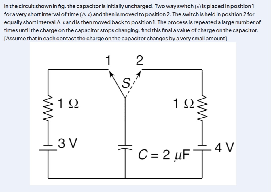
In the circuit shown in fig. the capacitor is initially uncharged. Two way switch (s) is placed in position 1 for a very short interval of time (Δ t) and then is moved to position 2. The switch is held in position 2 for equally short interval Δ t and is then moved back to position 1. The process is repeated a large number of times until the charge on the capacitor stops changing. find this final a value of charge on the capacitor. [Assume that in each contact the charge on the capacitor changes by a very small amount]
7 \mu C
Solution
The problem describes a circuit where a capacitor is repeatedly connected to two different voltage sources through resistors for very short intervals. The process continues until the charge on the capacitor reaches a steady state, meaning it no longer changes over a complete cycle of switching.
Let Q be the charge on the capacitor at any given time, and C its capacitance. The voltage across the capacitor is VC=Q/C.
Step 1: Analyze the circuit when the switch S is in position 1. When the switch is in position 1, the capacitor is connected to the 3V battery and the 1Ω resistor on the left. The current I1 flowing into the capacitor is given by Ohm's law: I1=R1V1−VC=1 Ω3 V−Q/C Since the switch is held for a very short interval Δt, the change in charge on the capacitor, ΔQ1, can be approximated as: ΔQ1=I1Δt=(3−CQ)Δt
Step 2: Analyze the circuit when the switch S is in position 2. When the switch is in position 2, the capacitor is connected to the 4V battery and the 1Ω resistor on the right. The current I2 flowing into the capacitor is given by Ohm's law: I2=R2V2−VC=1 Ω4 V−Q/C Since the switch is held for a very short interval Δt, the change in charge on the capacitor, ΔQ2, can be approximated as: ΔQ2=I2Δt=(4−CQ)Δt
Step 3: Determine the final charge on the capacitor. The process is repeated until the charge on the capacitor stops changing. This means that in the final steady state, the net change in charge over one complete cycle (position 1 for Δt then position 2 for Δt) is zero. Let Qf be this final charge. So, ΔQ1+ΔQ2=0. Substituting the expressions for ΔQ1 and ΔQ2 with Q=Qf: (3−CQf)Δt+(4−CQf)Δt=0 Since Δt is a non-zero interval, we can divide the equation by Δt: 3−CQf+4−CQf=0 7−2CQf=0 2CQf=7 Qf=27C
Step 4: Substitute the given values. The capacitance C=2μF=2×10⁻⁶ F. Qf=27×(2×10−6 F) Qf=7×10⁻⁶ C Qf=7μC
The final value of charge on the capacitor is 7μC.
The final answer is 7 \muC.
Explanation of the solution: The problem describes a switched-capacitor circuit reaching a steady state. In this state, the net change in charge on the capacitor over one complete switching cycle is zero.
- When the switch is in position 1, the current is I1=(3−Q/C)/1. The charge change is ΔQ1=I1Δt.
- When the switch is in position 2, the current is I2=(4−Q/C)/1. The charge change is ΔQ2=I2Δt.
- For the charge to stop changing, the total charge change over one cycle must be zero: ΔQ1+ΔQ2=0.
- This leads to (3−Qf/C)Δt+(4−Qf/C)Δt=0, which simplifies to 7−2Qf/C=0.
- Solving for Qf, we get Qf=7C/2.
- Substituting C=2μF, we find Qf=7μC.
Answer: The final value of charge on the capacitor is 7μC.