Question
Question: In the circuit shown, if \({V_{CE}} = 4{\text{V}}\) and \({R_B} = 200{\text{k}}\Omega \) , \({R_C} =...
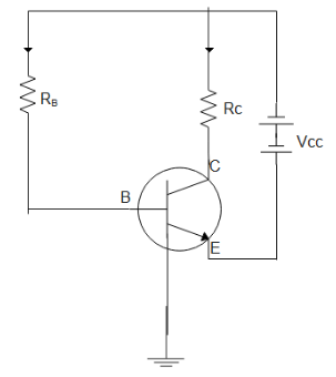
In the circuit shown, if VCE=4V and RB=200kΩ , RC=1kΩ, then find current gain.(VBE=0.4V)
Solution
The configuration in which the emitter is connected between collector and base is called C-E (common-emitter) configuration. In such a circuit, input is provided between emitter and base whereas the output is taken between emitter and collector. In such a circuit problem apply Kirchhoff’s law to find the value of required quantities.
Complete step by step answer:
Before applying Kirchhoff’s law to the loops in the circuit let us define Kirchhoff’s law first.According to Kirchhoff’s law, the total current entering the node is the same as the total current exiting the node. This is true for any node randomly chosen.
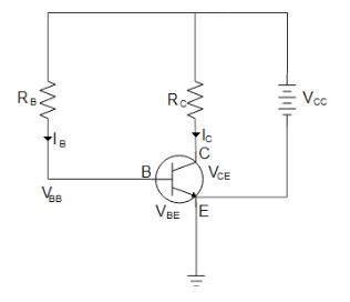
First applying Kirchhoff’s law to the right-hand arm of the circuit we get
VCC=VCE+ICRC
Substituting the values and rearranging we get,
10−IC×1×10³−4=0
Making current the subject of the equation
⇒IC=10310−4
⇒IC=6mA
Now applying Kirchhoff’s law to the left-hand arm of the circuit we get
VBB=VBE+IBRB
Substituting the values and rearranging we get,
10−IB×200×103−0.4=0
Making current the subject of the equation
⇒IB=200×10310−0.4
⇒IB=0.048mA
Therefore the current gain β is
β=IBIC
Substituting the values we get,
∴β=125
Hence, the current gain is 125.
Additional information: In common emitter circuits, we get a large value of voltage gain and power gain whereas current gain is moderate. This ability of common emitter circuits is harnessed in developing advanced BJT where we get a stable and steady voltage supply, even though there is varying current gain.
Note: For solving such questions we need to apply Kirchhoff’s law separately to both arms. And we should be careful with the sign used for current and voltage. And to decide the type of configuration of the transistor we should see which arm of the transistor is grounded in the circuit diagram. The one which is grounded will be common in the configuration.