Question
Question: In the circuit shown, each resistance is 2 $\Omega$. The potential $V_1$ (in volt) as indicated in t...
In the circuit shown, each resistance is 2 Ω. The potential V1 (in volt) as indicated in the circuit, is equal to:
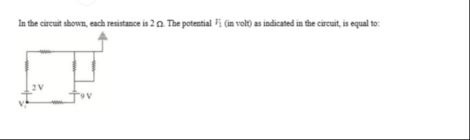
-9
Solution
The circuit can be analyzed using Kirchhoff's Current Law (KCL) at various nodes. Let's assign potentials to the key nodes.
- Let the potential at the top arrow (which is usually considered ground in such problems unless specified otherwise) be VG=0V.
- Let the potential at the central junction where three resistors meet be VX.
- Let the potential at the node between the 2V battery and the first resistor in that branch be VA.
- Let the potential at the node between the two resistors in the 2V battery branch be VB.
- Let the potential at the node between the 9V battery and the resistor connecting to VX be VC.
- The potential V1 is at the bottom left. Let's use it as V1.
- Let the potential at the node between V1 and the 9V battery be VD.
All resistances are R=2Ω.
From the diagram, we can establish the following relationships:
- The positive terminal of the 2V battery is connected to node VA. The negative terminal is at V1. So, VA=V1+2.
- The positive terminal of the 9V battery is connected to node VC. The negative terminal is at VD. So, VC=VD+9.
Now, let's write KCL equations for the nodes VX, VB, and VD. Assume currents leaving a node are positive.
KCL at Node VX:
The resistors connected to VX are:
- One to ground (VG=0V).
- One to VB.
- One to VC.
The sum of currents leaving VX is zero:
RVX−VG+RVX−VB+RVX−VC=0Substitute VG=0 and VC=VD+9:
RVX−0+RVX−VB+RVX−(VD+9)=0Multiply by R:
VX+VX−VB+VX−VD−9=0 3VX−VB−VD=9(Equation 1)KCL at Node VB:
The resistors connected to VB are:
- One to VX.
- One to VA.
The sum of currents leaving VB is zero:
RVB−VX+RVB−VA=0Substitute VA=V1+2:
RVB−VX+RVB−(V1+2)=0Multiply by R:
VB−VX+VB−V1−2=0 2VB−VX−V1=2(Equation 2)Current relationship in the 9V battery branch:
The current flowing through the resistor between VC and VX is the same as the current flowing through the 9V battery and the resistor between VD and V1.
Let I be the current flowing from VC to VX.
I=RVC−VXThis same current I flows from VD to V1 through the resistor RD−1.
I=RVD−V1Therefore,
RVC−VX=RVD−V1 VC−VX=VD−V1Substitute VC=VD+9:
(VD+9)−VX=VD−V1 VD+9−VX=VD−V1 9−VX=−V1 VX−V1=9(Equation 3)Now we have a system of three linear equations with three unknowns (V1,VB,VX,VD). We need to eliminate VB and VD to find V1.
From Equation 3, express VX in terms of V1:
VX=V1+9Substitute VX into Equation 2:
2VB−(V1+9)−V1=2 2VB−2V1−9=2 2VB=2V1+11 VB=V1+211(Equation 4)Substitute VX into Equation 1:
3(V1+9)−VB−VD=9 3V1+27−VB−VD=9 3V1−VB−VD=9−27 3V1−VB−VD=−18(Equation 5)Substitute VB from Equation 4 into Equation 5:
3V1−(V1+211)−VD=−18 3V1−V1−211−VD=−18 2V1−VD=−18+211 2V1−VD=2−36+11 2V1−VD=−225 VD=2V1+225(Equation 6)Now, consider the current flowing through the 2V battery branch.
The current flowing from VA to VB is IA−B=(VA−VB)/R.
This is the same current that flows through the 2V battery. So, I1−A=IA−B.
The current flowing from V1 to VA through the battery means I1−A=(V1−VA+2)/R if we consider the battery as a voltage source with no internal resistance.
However, we have already used the potential relationships VA=V1+2.
The current from V1 to VA is not directly through a resistor.
The current flowing out of V1 goes into the 2V battery and into the resistor R1−D.
Let's apply KCL at V1.
Current leaving V1 towards the 2V battery: Let this be I1→battery.
Current leaving V1 towards VD: (V1−VD)/R.
Sum of currents leaving V1 must be zero.
I1→battery+RV1−VD=0.
Let's find I1→battery. This current flows from VA through the resistor RA−B to VB, and then from VB through RB−X to VX.
So, I1→battery=IA−B=RVA−VB.
I1→battery=R(V1+2)−VBSubstitute VB=V1+211:
I1→battery=RV1+2−(V1+211)=R2−211=R24−11=R−7/2=−2R7This means the current I1→battery is actually flowing into V1 from the battery branch.
Now, apply KCL at V1:
Current flowing into V1 from the 2V battery branch is 7/(2R).
Current flowing out of V1 into the resistor R1−D is (V1−VD)/R.
So,
2R7+RV1−VD=0Multiply by R:
27+V1−VD=0 VD=V1+27(Equation 7)Now we have two expressions for VD (Equation 6 and Equation 7). Let's equate them:
2V1+225=V1+27 2V1−V1=27−225 V1=27−25 V1=2−18 V1=−9VThe potential V1 is -9 Volt.