Question
Question: In the circuit shown below, \({C_1} = 10\mu F\), \({C_2} = {C_3} = 20\mu F\), and \({C_4} = 40\mu F\...
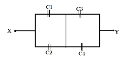
In the circuit shown below, C1=10μF, C2=C3=20μF, and C4=40μF. If the charge on C1 is 20μF, then the potential difference between X and Y is:
A) 2V
B) 3V
C) 6V
D) 3.5V
Solution
when capacitors are in series connection, the ratio of their capacitance is equal to the ratio of the charge passing through them. This relation helps us find the value of charge through C2. We will use this charge value in determining the potential difference across C2. Also, the sum of their charges will be equal to the total charge on their positive plates.
As C3 and C4 are in series, the resultant of their capacitance will be additive. Because charge in a circuit will be constant, the charge found out in the loop of C1 and C2 is the charge in the loop of C3 and C4. Thus we will be able to find out the potential difference across C3.
Therefore, we will add both the potential difference and find out the given circuit’s potential difference value.
Formulae used: Ratio of their capacitance in C1 and C2 is equal to the ratio of the charge passing through them:
Q2Q1=C2C1
Where C1 and C2 are the capacitance values and is expressed in microFarads(μF) and Q1 and Q2 are the charge values and is expressed in microCoulombs (μC).
Sum of their charges: Q=Q1+Q2
Where Q is the sum of charge on their positive plates of C1 and C2.
Potential difference across C2: V2=C2Q2
Where V2 is the potential difference value across C2 and is expressed in volts (V).
Resultant of their capacitance of C3 and C4: C3+C4
Where C3 and C4 are the capacitance values and are expressed in microFarads(μF).
Potential difference across C3: V3=C3+C4Q1+Q2
Where is the potential difference value across C3 and is expressed in volts (V).
Given circuit’s potential difference value: V=V2+V3
Where Vis the potential difference values of the entire circuit and is expressed in volts (V).
Complete step by step solution:
From the given circuit we determine that C1 & C2 and C3 & C4 are in parallel connection with each other’s loops. And C1 & C2 and C3 & C4 are in series among themselves.
Let, Q1,Q2,Q3,Q4be the charges on C1,C2,C3,C4.
We know that for capacitors in series connection, the ratio of their capacitance is equal to the ratio of the charge passing through them.
Therefore, Q2Q1=C2C1 .
Substituting the values we get,
The potential difference across Q2 is C2Q2.
Substituting the values we get,
V2=C2Q2=2040
⇒V2=2V
Also, the total charge on the positive plates of C1 and C2 Q=Q1+Q2
Substituting the values we get,
Q=20+40 ⇒Q=60μC
For the second loop of capacitors which are connected in series, the summation of their capacitances is C3+C4.
Substituting the values we find the total capacitance of the loop to be 20+40=60μF.
We know that the amount of charge entering a circuit through one end is equal to the amount of charge exiting through the other end.
Therefore we can determine the potential difference across C3 to be V3=C3+C4Q1+Q2.
Substituting the values we get,
Finally we can calculate the potential difference across X and Y with V=V2+V3.
Substituting the values we get the potential difference values of the entire circuit,
V=V2+V3=2V+1V ⇒V=1V
Additional information: capacitors are used to store charge for future requirement of a circuit. Therefore, we add the capacitance value for two capacitors in series connection.
In conclusion, the potential difference between X and Y is 1V.
Note: The charge is conserved in a given system. Calculating it only for the first loop will be sufficient. Double calculation will lead to error in further calculations involving charge.