Question
Question: In the circuit given below (a) and (b), the switches \({{S}_{1}}\) and \({{S}_{2}}\) are closed at \...
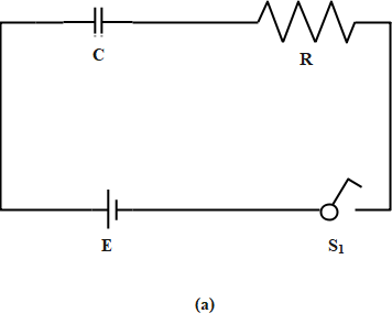
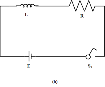
In the circuit given below (a) and (b), the switches S1 and S2 are closed at t=0 and they are kept closed for a long time. The change in the values of the currents in the two circuits for t≥0 will be roughly shown as (the diagrams given are schematic and not drawn to scale).
A.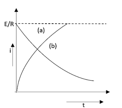
B.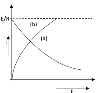
C.
D.
Solution
At the initial time the resistance offered by a capacitor will be zero. Therefore the current in the capacitor will be maximum. As time goes the resistance will get increased and reaches a maximum value. Similarly for an inductor, at the initial time, the resistance will be infinite and current will be the minimum. As time goes, resistance get decreased also.
Complete answer:
As we all know that in a capacitor circuit at time t=0, the capacitor will act as zero resistance and the current will be the maximum. This means that the ratio of the electric field to the value of the resistance will be a constant. This can be written as,
RE=constant
And then after infinite time, the capacitor will provide an infinite resistance like an open circuit and the current in the circuit will be zero.
In an inductive circuit at a time t=0, the inductor acts like having an infinite resistance and the current will be zero in the circuit. Then after an infinite time, the capacitor will act like having zero resistance and current in the circuit will be the maximum. That is RE. According to the data we have discussed now, the graph will be obtained as,
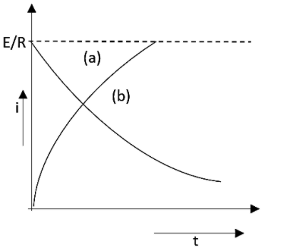
This has been given as option A.
Note:
A capacitor is an electrical device which is used to store the electrical energy in between two metal plates. This can work in the circuit having an alternate current supply. An inductor is another electrical device in order to store the magnetic field.