Question
Question: In the circuit diagrams (A, B, C and D) shown below, R is a high resistance and S is a resistance of...
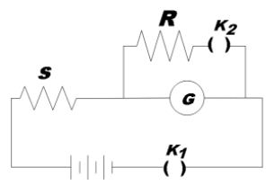
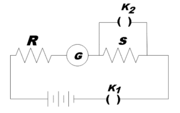
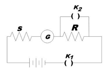
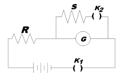
In the circuit diagrams (A, B, C and D) shown below, R is a high resistance and S is a resistance of the order of galvanometer resistance G. The correct circuit, corresponding to the half deflection method for finding the resistance and figure of merit of the galvanometer, is the circuit labeled as:
A.
B.
C.
D.
Solution
You could recall the expression that we use while calculating the galvanometer resistance from a circuit by half deflection method. Thus find out which among the given circuits has the possibility to give the same expression. Also, derive the same expression from the circuit as a justification to your answer.
Formula used:
Galvanometer resistance,
G=R−SRS
Complete answer:
If you may recall, the expression used for finding the galvanometer resistance G is by,
G=R−SRS …………………………… (1)
Only the circuit given in option D can satisfy the relation. In order to justify the same, consider the circuit.
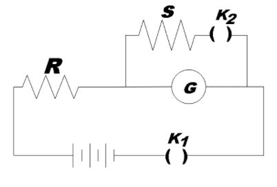
When key 1 is closed with key 2 open with voltage E, by ohm’s law, the current through the circuit is given by,
I1=R+GE
But we know that the current flowing through the galvanometer is proportional to the deflection it shows. So,
I1∝θ
⇒R+GE=kθ …………………………… (2)
Now when key2 is closed, the galvanometer will show 2θ deflection if the value of shunt is almost equal to G. So, the current in the circuit now will be,
I2=R+G+SGSE …………………………………. (3)
By current division rule, we know that the current passing through the galvanometer is given by,
Ig=G+SI2S=k2θ
Substituting (2) and (3),
G+SR+G+SGSES=2R+GE
⇒R(G+S)+GSS=2(R+G)1
⇒RS+GS=RG
∴G=R−SRS
Therefore, we get the same expression for G as in (1).
Hence, we could confirm that option D is the correct circuit diagram.
Note:
The basic idea here is that the shunt is connected in the circuit so as to make the galvanometer to show a deflection of 2θ. Also, in the equation (1), if R was really greater than S (R≫S)then,
G=R−SRS≈RRS
∴G≈S
This should explain the current being equally divided between G and S.