Question
Question: In the circuit diagram shown in the figure, the magnitude and direction of the flow of current, resp...
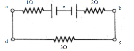
In the circuit diagram shown in the figure, the magnitude and direction of the flow of current, respectively would be:
(A) 37A from a to e
(B) 37A from b to
(C) 1A from b to e
(D) 1A from e to b
Solution
We know that in a series circuit, the equivalent resistance is the algebraic sum of the resistances. The current through the circuit can be found from Ohm's law and is equal to the voltage divided by the equivalent resistance. The potential drop across each resistor can be found using Ohm's law. The method we use to calculate equivalent resistance is different for each type of circuit. For a series circuit, we simply add up the resistances of each component. However, in a parallel circuit, the reciprocal of the total resistance is equal to the sums of the reciprocals of the resistances of each branch.
Complete step by step answer
We know components connected in series are connected along a single conductive path, so the same current flows through all of the components but voltage is dropped (lost) across each of the resistances. In a series circuit, the sum of the voltages consumed by each individual resistance is equal to the source voltage.
In a parallel circuit, all components are connected across each other, forming exactly two sets of electrically common points. A “branch” in a parallel circuit is a path for electric current formed by one of the load components (such as a resistor).
There is no division of voltage among the appliances when connected in parallel. The potential difference across each appliance is equal to the supplied voltage. The total effective resistance of the circuit can be reduced by connecting electrical appliances in parallel.
Total R of circuit = 1 + 2 + 3 = 6 Ω
The formula can be justified as the current in the circuit will always be equal to the ratio of the effective voltage and the effective resistance.
Now in the formula that is given above we have to put the values from the question to get the expression as:
After we put the values, we get that:
The current in the circuit = effective resistanceeffective voltage=6Ω6V=1A
As 10 V is greater, the current direction will be from the positive terminal of 10 V to the positive terminal of 4 V.
So the direction of the current can be explained as: a terminal to d, then to terminal c, then to terminal b, then to terminal e and finally to terminal a.
Thus we can write that direction of current would be from a to b via e.
So, the correct answer is option D.
Note We know that the most common everyday series circuits are the electrical circuits found in homes and vehicles, with the difference being the type of voltage used in each one. Series circuits are used in areas where the operation of the circuit is required to be linear. Water heaters use a series circuit. The two ways to connect components in a circuit are in series and in parallel. In a series connection, components are connected end to end, so that current flows first through one, then through the other. In the series connection, the current goes through one lamp and then the other. In a series circuit, the current is the same at each resistor. The voltage drop will be the same for each resistor since the current at and the resistance of each resistor is the same. Thus, the electric potential difference across any one of the bulbs will be the same as that across any one of the other bulbs.