Question
Question: In the adjacent diagram A and B represents two inputs and C represent the output, the circuit repres...
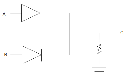
In the adjacent diagram A and B represents two inputs and C represent the output, the circuit represents
(A). NOR gate
(B). AND gate
(C). NAND gate
(D). OR gate
Solution
The given circuit connects diodes to form a gate. When we apply potential difference across the diodes, we get a certain output at C. The inputs given and the output received as a result from the given circuit can be used to make a truth table. The truth table will tell us the type of gate formed by the circuit.
Complete answer:
A diode is a semiconductor device which allows the current to flow in one direction.

In the figure given above, A and B are diodes. If a potential difference is applied across AB such that A is positive. Then, potential at A is equal to potential at C. Therefore,
A=C
Similarly, if B is positive, the potential at B will now be equal to potential at C. Therefore,
B=C
If there is no potential at both A and B, then there will be no potential at C. Therefore,
C=0
Its truth table can be drawn as
| A | B | C |
|---|---|---|
| 1 | 0 | 1 |
| 0 | 1 | 1 |
| 0 | 0 | 0 |
The above given table is a table of an OR gate. Thus, the given setting represents an OR gate.
Therefore, the above circuit represents an OR gate. Hence, the correct option is (D).
Note:
Gates are a combination of diodes and are basic blocks of any digital system which take binary inputs to give one binary output. A binary number is expressed in base 2 and uses only 0 and 1. More complex gates can be made by combining simple gates. Earth is a conductor of electricity that is still complete when the load is grounded.