Question
Question: In the adjacent circuit diagram, initially switch S is opened and the circuit is in steady state. At...
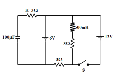
In the adjacent circuit diagram, initially switch S is opened and the circuit is in steady state. At time t = 0, the switch S is closed and the steady state is reached. Choose the correct option (s).
a) Current in the inductor when the circuit reaches the new steady state is 4A.
b) The net change in the magnetic flux in the inductor is 1.5Wb.
c) The potential difference across the inductor is 9 volt when the circuit reaches the new steady state.
d) The charge stored in the capacitor in the new steady state is 1.2mC.
Solution
In the steady state when a capacitor is connected to a dc supply, the capacitor offer’s an infinite resistance and hence there is no flow of current across the capacitor. Similarly the inductor in steady state offers no resistance in the circuit and therefore it can just be considered as a wire. Hence using these conditions and Kirchhoff’s loop rule, we will analyze all the above options and obtain the correct option
Complete step-by-step solution:
As soon as the key ‘S’ is closed, there is a steady state attained. In the steady state, the capacitance offer’s and infinite resistance resulting in no flow of current. The inductor in steady state does not offer any resistance. Therefore the above circuit in steady state can be more precisely drawn as,
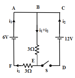
From the above circuit diagram, we have taken the direction of current i1 from the source i.e. 6V and current i2 from the source 12V. The direction of current is according to Kirchhoff’s junction rule.
Applying Kirchhoff’s voltage law to the loop ABEF, we obtain
6V=(i1+i2)3Ω+i13Ω.......(1)
Similarly applying the Kirchhoff’s voltage law for loop BCED, we get
12V=(i1+i2)3Ω......(2)
Subtracting equation 1 from 2 we obtain,
12V−6V=(i1+i2)3Ω−[(i1+i2)3Ω+i13Ω]⇒6V=−i13Ω∴i1=−2A
Substituting the value of i1 equation in equation 2 we obtain,
12V=(i1+i2)3Ω⇒312=(−2+i2)⇒4=(−2+i2)∴i2=6A
Hence the current across the inductor i.e. i1+i2 is equal to,
i=i1+i2∴i=−2A+6A=4A
Therefore the correct answer of the above question is option B.
Note: The Kirchhoff’s voltage law states that if we trace a closed loop in a circuit, the sum of the potential difference across the resistors in the circuit is equal to the sum of emf of the cell in the loop. If the path traced is in the direction of current then the potential difference across the resistors is taken as positive and the emf is taken as positive if we move across the cell from the negative to positive terminal of the cell. Similarly Kirchhoff’s junction rule states that the amount of current entering the junction is equal to that leaving the junction.