Question
Question: In the above shown circuit diagram, across which resistor (s)will the voltmeter correctly read the v...
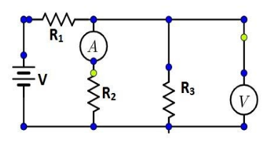
In the above shown circuit diagram, across which resistor (s)will the voltmeter correctly read the voltage?
(A) R1,R2, and R3 only
(B) R1 only
(C) R2 only
(D) R3 only
(E) R2 and R3 only
Solution
A voltmeter measures potential difference across resistors. Its working principle requires it to be connected in parallel to the resistors. In parallel connection, the voltage is the same so the voltage between the voltmeter and the load is almost the same.
Complete Answer:
A voltmeter is an instrument used for measuring electric potential difference between two points in an electric circuit. It is connected in parallel. It usually has a high resistance so that it takes a negligible current from the circuit.
As can be seen from the figure given, two resistors R2 and R3 are connected in parallel to one another and to a voltmeter. An ammeter is connected in series with the resistance R2 and the resistor R1 is connected in series to both the resistors.
The main principle of voltmeter is that it must be connected in parallel in which we want to measure the voltage. Parallel connection is used because a voltmeter is constructed in such a way that it has a very high value of resistance. So if that high resistance is connected in series then the current flow will be almost zero meaning that the circuit would be open.
If connected in parallel, then the load impedance comes parallel with the high resistance of the voltmeter and hence the combination will give almost the same impedance that the load had. Also in parallel circuits we know that the voltage is the same so the voltage between the voltmeter and the load is almost the same and hence the voltmeter measures the voltage.
For the circuit diagram given, potential drop across an ideal ammeter is zero.
Thus, the voltmeter measures voltage correctly for the resistors R2 and R3.
Then the correct answer is Option E.
Note:
An ammeter is a measuring instrument used to measure the current in a circuit. Electric currents are measured in amperes, hence the name. The ammeter is usually connected in series with the circuit in which the current is to be measured.
For an ideal voltmeter, we have the resistance to be infinity and hence the current drawn to be zero so there will be no power loss in the instrument. But this is not achievable practically as we cannot have a material which has infinite resistance.