Question
Question: In the above circuit, \(C=\dfrac{\sqrt{3}}{2}\mu F\), \({{R}_{2}}=20\Omega \), \(L=\dfrac{\sqrt{3}}{...
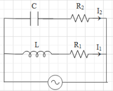
In the above circuit, C=23μF, R2=20Ω, L=103H and R1=10Ω. Current in L−R1 path is I1 and C−R2 path it is I2. The voltage of the AC source is given by V=2002sin(100t) volts. The phase difference between I1 and I2 is:
A. 30∘
B. 0∘
C. 150∘
D. 60∘
Solution
Make use of the equation given for the voltage of an AC source and find the angular frequency of the circuit. Then draw the phasor diagram for both the path and find the phase between the current and the main voltage in both paths.
Formula used:
V=V0sin(ωt)
⇒VR1=I1R1
⇒VL=I1XL
⇒XL=ωL
⇒VC=ICXC
⇒XC=ωC1
Here, V0 is the amplitude,ω is the angular frequency, XL is the reactance of the inductance, R1, R2 are resistances, XC is the reactance of the capacitor, C is capacitance and L is inductance.
Complete step by step answer:
The equation for voltage of the source is given as V=V0sin(ωt), where V0 is the amplitude and ω is the angular frequency.It is given that the voltage of the AC source is V=2002sin(100t).This means that ω=100s−1. In the diagram of the circuit, we can see that the capacitor and the resistance R1 in series connection and the inductor and the resistance R2 are also in series connection. Then these both pairs are connected in parallel to an AC source.Let us first the phase diagram for the L−R1 path.The current in this path is said to be I1. When an inductor and a resistance are in series connection, then the voltage across the resistance is in phase with the circuit flowing in that path and the voltage across the inductance leads over current by an phase angle of 2π.
The voltage across the resistance R1 is equal to VR1=I1R1.
The voltage across the inductor is VL=I1XL, where XL is the reactance of the inductance. And XL=ωL, where ω is the angular frequency of the source and L is the inductance.Therefore, the phase diagram for the L−R1 path will look like:
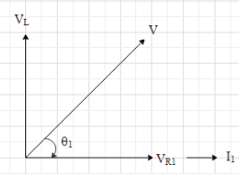
Here V is the amplitude of the source. And it is given that V=2002volts.
From the figure, we get that tanθ1=VR1VL=I1R1I1XL=R1XL
⇒tanθ1=R1ωL
Substitute the given values.
⇒tanθ1=10100×103=3
⇒θ1=tan−13=60∘
Now, let us draw the phase diagram for the C−R2 path.The current in this path is said to be I2. When a capacitor and a resistance are in series connection, then the voltage across the resistance is in phase with the circuit flowing in that path and the voltage across the inductance lags current by an phase angle of 2π.
The voltage across the resistance R2 is equal to VR2=I2R2.
The voltage across the capacitor is VC=ICXC, where XC is the reactance of the capacitor.
And XC=ωC1, where C is the capacitance.
Therefore, the phase diagram for the L−R1 path will look like:
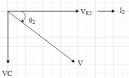
Here the net voltage will be V since both the paths are parallel with the same voltage source.From the figure, we get that tanθ2=VR2VC=I2R2I2XC=R2XC
⇒tanθ2=R2ωC1=ωCR21
Substitute the given values.
⇒tanθ2=100×23×10−6×101=32×103=1154.7
⇒θ2=tan−1(1154.7)≈90∘.
From the phasor diagram, we can understand that the phase difference between I1 and I2 is θ1+θ2=60∘+90∘=150∘.
Hence, the correct option is C.
Note: For solving AC circuit, phasor diagrams are used. Here, we do not treat the voltages and current as scalars rather we treat them as vectors. The magnitudes of the vector are equal to the amplitude of the corresponding wave.Since the voltages and current continuously change with time in an AC circuit, we cannot add them algebraically.