Question
Question: In showing figure find \({V_R}\) : 
A. 132 V
B. 396 V
C. 185 V
D. 220×176 V
Solution
We are given a circuit containing a resistor and an inductor and a voltage source and we need to find the voltage through the resistor. We can use a phasor diagram for an LR circuit to get the value of voltage through the resistor.
Complete step by step answer:
We will draw a phasor diagram for a resistor-inductor to calculate the voltage through the resistor. We will take current as the reference and will draw the voltage drop across the resistance in phase with the current. And we will draw the voltage across the inductor ahead of the current with a phase difference of 90∘ because of current lag voltage in a purely inductive circuit. The vector sum of two voltage drops will be equal to the applied voltage.
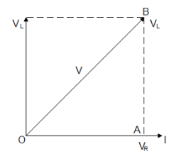
From the figure, we get in the right-angled triangle OAB
VR=IR and VL=IXL where XL=2πfl
Now V=(VR)2+(VL)2
⇒VR=V2−VL2
Substituting the given values we get
⇒VR=2202−1762
∴VR=132 V
Hence option A is the correct answer.
Additional information: Phasor diagrams are diagrams representing alternating current and voltage as vectors with the phase difference between them. Phasors are rotating vectors but they represent scalar quantities. Thus a sinusoidal alternating current and voltage can be represented by rotating vectors. The length of the vector is equal to the peak value of alternating voltage or current.
In purely inductive circuits when current reaches its maximum value after voltage becomes maximum then-current lags behind the voltage. And in a purely inductive circuit, when current reaches its maximum value before the voltage reaches its maximum then-current leads ahead voltage. And in purely resistive circuits, the current and voltage are in the same phase when they reach their maximum value.
Note: The circuit that is given to us is an LR circuit that means it contains only an inductor and a resistor and thus the current lags behind voltage so we need to be careful while drawing the phasor diagram for the circuit. And since we are treating the current and voltage as vectors so we use the vector property of shifting and we apply the Pythagoras theorem to the triangle formed.