Question
Question: In an RL Series circuit, sinusoidal voltage \[v = {v_0}\;sin\;\omega t\] is applied. it is given tha...
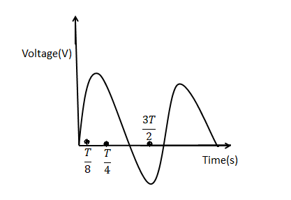
In an RL Series circuit, sinusoidal voltage v=v0sinωt is applied. it is given that 2T, R=11Ω, Vrms=220 V, 2πω=50 Hz and π=722. Obtain the phase difference between the current and voltage and find the amplitude of current in the steady state. Plot the variation of current for one cycle on the given graph.
Solution
A LR Circuit consists of an inductor of inductance L connected in series with a resistor of resistance R. First find the inductive reactance then find the maximum current flowing in the circuit. In the above waveform, time period is given as 2π.Then from data obtained we can plot the variation of current for one cycle on the given graph.
Formula used:
XL=ωL
Irms=R2+X2Vrms
Imax=Irms×2
Where XL is the inductive reactance, R is the resistance, Imax is the maximum current,Irms is the root mean square current.
Complete step by step answer:
LR circuit consists of a resistor of resistance R connected in series with an inductor L .VR is equal to IR due to the voltage drop across the resistor. Hence it will have the same exponential shape and growth as the current. Just like RC and LCR circuit, RL circuit will also consume energy.
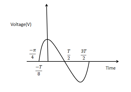
The current and voltage are in the same phase and the phase angle difference between current and voltage is zero, in case of resistors. The current and the voltage are not in phase. The current lags voltage by 90∘. As seen before the phase angle between voltage and current is zero in case of pure resistance circuit and phase angle90∘ in case of pure inductive circuit. But when we combine both resistance and inductor, LR circuit phase angle is between 0∘to90∘.
XL=ωL$ = 2\pi \times 50 \times 35 \times {10^{ - 3}} = 11\Omega \left( {1mH = 1 \times {{10}^{ - 3}}H} \right){I_{rms}} = \dfrac{{{V_{rms}}}}{{\sqrt {{R^2} + {X^2}} }}{I_{rms}} = \dfrac{{220}}{{\sqrt {\left( {{{11}^2} + {{11}^2}} \right)} }} = {I_{rms}} = \dfrac{{220}}{{\sqrt {\left( {{{11}^2} + {{11}^2}} \right)} }} = \dfrac{{20}}{{\sqrt 2 }}AThenthemaximumcurrentisgivenby{I_{\max }} = {I_{rms}} \times \sqrt 2 = \dfrac{{20}}{{\sqrt 2 }} \times \sqrt 2 = 20A\tan \phi = \dfrac{{{X_L}}}{R} = \dfrac{1}{1} = 1Therefore,thevalueof\phi is\dfrac{\pi }{4}ThenthesinusoidalcurrentequationisgivenbyI = {I_{\max }}\sin \left( {\omega t + \phi } \right) = 20\sin \left( {\omega t + \dfrac{\pi }{4}} \right)$
Note: A LR Circuit consists of an inductor of inductance L connected in series with a resistor of resistance R. The impedance of LR circuit opposes the flow of alternating current. The flow of alternating current opposed by the impedance of LR circuit. LR circuit phase angle is between 0∘ to 90∘. Just like RC and LCR circuit, LR circuit will also consume energy.