Question
Question: In an \[LCR\] series a.c. circuit, the voltage across each of the components \[L,{\text{ }}C\] and \...
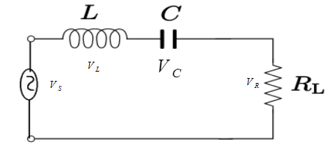
In an LCR series a.c. circuit, the voltage across each of the components L, C and R is 50 V. The voltage across the LC combination will be:
A) 50V
B) 502V
C) 100V
D) 0V (zero)
Solution
In LCR series a.c circuit, the components L, C and R are related to each other in a way that the voltage across the inductor L(VL) and voltage across the capacitor C(VC) has a constant phase difference. The voltage across the resistance R(VR) and current(i) does not have any phase difference.
Complete step by step solution:
According to the question, a LCR series a.c. circuit is given. The voltage across L, C and R is 50 V.
We know that in an LCR series circuit, the voltage across the inductor L(VL) leads the current(i) by 90∘ and voltage across the capacitor C(VC) lags the current(i) by 90∘. So, the inductance and the capacitance are in opposite phases. In an LCR series circuit, the voltage across the resistance R(VR) is in the same phase with current(i).
So, the voltage across the LC combination will be given as:
VLC=VL−VC ⇒VLC=50−50 ⇒VLC=0
To understand the phase difference in different voltages, we can make a graph which shows the phase difference between voltages.
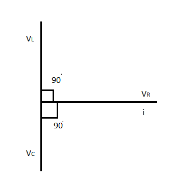
According to the above graph, VR and i are in the same phase. VLleads current i by 90∘ and VC lags current i by 90∘. So, the voltage across LC combination is zero.
Hence, option (D) is correct.
Note: Voltage across the inductor VL and current i has a phase difference. Voltage across the capacitor VC and current i has a phase difference. The voltage across the resistance VR and current i has zero phase difference. According to the graph, current i and voltage across the resistance VR are plotted on X-axis.