Question
Question: In an experiment to determine the resistance of a galvanometer by half deflection method, the circui...
In an experiment to determine the resistance of a galvanometer by half deflection method, the circuit shown is used. In one set of readings, if R=10Ω and S=4Ω, then the resistance of the galvanometer is
A. 320ΩB. 340ΩC. 350ΩD. 310Ω
Solution
A galvanometer is an electronic device used to detect feeble electric current flowing in a circuit. It consists of a magnetic coil suspended between the poles of a powerful magnet. As current passes through the coil, it deflects. Its motion can be detected from the deflection in the galvanometer needle. The deflection is proportional to the current passed through the galvanometer.
Complete step by step answer:
A galvanometer is a type of an electromechanical device which is used for detecting and indicating an electric current through a circuit. A galvanometer basically works like an actuator, by producing a rotatory deflection of the pointer, in response to the electric current flowing through a coil placed in a uniform and constant magnetic field. It is a sensitive device which can measure low currents even of the order of a few microamperes.
Principle of working of galvanometer – A current carrying coil when placed in an external magnetic field experiences magnetic torque. The angle by which the coil is deflected due to the effect of the magnetic torque is proportional to the magnitude of current in the coil.
Half-deflection method for measuring the current through the galvanometer:
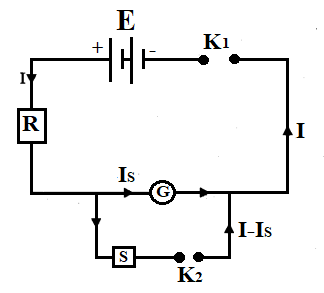
When key K1 is closed, the current through the galvanometer is,
IG=R+GE
(Let’s say equation 1)
If θ is the deflection shown in the galvanometer due to the flow of current IG , then,
IG∝θ
Or,
IG=kθ
(Let’s say equation 2)
Where,
k is known as the figure of merit
Using equation 1 and equation 2,
R+GE=kθ
(Let’s say equation 3)
When key K2 is closed, the current through the galvanometer is,
(IG)′=G+SS×I
Where,
I is the current flowing in the main circuit
Now,
The value of S is adjusted in a way that the deflection θ will be half, that is, 2θ
Thus,
(IG)′=k(2θ)
Put (IG)′=G+SS×I
We get,
⇒G+SS×I=k(2θ)
(Let’s say equation 4)
Total resistance of the circuit is given as,
Rt=R+S+GSG
Thus,
I=RtE
Put Rt=R+S+GSG
We get,
⇒I=R+S+GSGE
(Let’s say equation 5)
Diving equation 4 by equation 3,
R+GEG+SS×I=kθk(2θ)
Or,
(G+S)ESI(R+G)=21
(Let’s say equation 6)
Now,
Substituting the value of I in equation 6 using the equation 5,
I=R+S+GSGE
Solving above,
SR+S+GSGE(G+S)E(R+G)=21
⇒SS+GR(S+G)+SGE(G+S)E(R+G)=21
R(S+G)+SGS(R+G)=21
⇒2S(R+G)=R(S+G)+SG
⇒2S(R+G)=S(R+G)+RG
⇒S(R+G)=RG
⇒RS=G(R−S)
⇒G=R−SRS
We get,
⇒I=R+S+GSGE
We get,
⇒G=R−SRS
Putting the given values,
R=10ΩS=4Ω
We get,
⇒G=10−410×4=640
⇒G=320Ω
The resistance of the galvanometer is 320Ω
Hence, the correct option is A.
Note:
A resistor having a very small value of resistance is called a Shunt resistance and it is always connected in parallel in a circuit. Shunt resistance is used for converting a galvanometer into ammeter as most of the current will flow through it and only a small fraction of current will flow through the galvanometer, which is sufficient to make a deflection. Figure of merit is a numerical that represents the degree of efficiency or effectiveness of an instrument approximated by the different estimation techniques.