Question
Question: In a circuit shown in figure if the internal resistance of the sources are negligible then at what v...
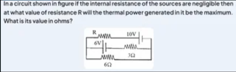
In a circuit shown in figure if the internal resistance of the sources are negligible then at what value of resistance R will the thermal power generated in it be the maximum. What is its value in ohms?
2
Solution
The circuit diagram shows a resistor R connected in series with a parallel combination of two branches. The first branch consists of a 6V battery in series with a 6Ω resistor. The second branch consists of a 10V battery in series with a 3Ω resistor. The internal resistances of the sources are negligible.
We want to find the value of resistance R for which the thermal power generated in it is maximum. The thermal power generated in R is given by P=I2R, where I is the current flowing through R.
We can simplify the circuit connected to R using Thevenin's theorem. Let the terminals across which R is connected be A and B. From the diagram, it appears that R is connected between some point and node B. Let's assume R is connected between node A and node B. Node B is the common negative terminal of the two batteries and the bottom ends of the 6Ω and 3Ω resistors. Node A is connected to one end of R. The other end of R is connected to the point where the two branches are connected in parallel. Let's call this point C. Then R is connected between A and C. The parallel combination of the two branches is connected between C and B. Let's assume the resistor R is connected in series with the parallel combination of the two branches. So, the current from the parallel combination flows through R.
Let's find the Thevenin equivalent circuit between points C and B. The open-circuit voltage VCB,oc: Consider the two branches in parallel between C and B. Let VC and VB be the potentials at C and B. Let VB=0. In the first branch, VC−I1×6−6=VB=0, so VC=6I1+6. In the second branch, VC−I2×3−10=VB=0, so VC=3I2+10. Since C and B are open-circuited (no R connected yet), the current flowing out of C into the branches must sum to zero if there is no current entering C. However, if R is connected in series with the parallel combination, then the current through R enters the parallel combination at C.
Let's assume the intended circuit is that R is connected in series with the parallel combination of the two branches. Let the current flowing out of the parallel combination at C be I, and this current flows through R. The parallel combination is connected to node B. So, the current I flows through R and then enters the parallel combination at C and leaves at B. This interpretation seems incorrect based on the diagram.
Let's go back to the first interpretation based on the diagram where R is connected between the top wire and the common bottom wire. Let the top wire be node A and the bottom wire be node B. The two branches are connected between A and B. The resistor R is connected in series with the parallel combination of these two branches. This also does not match the diagram.
Let's assume the diagram represents R in series with the parallel combination of the two branches. Let the two branches be connected between points X and Y. Then R is connected in series with the equivalent resistance between X and Y. However, the diagram shows R connected at the top.
Let's assume the diagram shows that R is connected between the top node and the junction of the two branches. Let the top node be A, the junction of the two branches be C, and the bottom node be B. So, R is connected between A and C. The two branches are connected between C and B.
Let's assume the circuit is as follows: R is connected in series with the parallel combination of the two branches. The two branches are connected between two nodes. Let's call the top node X and the bottom node Y. Branch 1: 6V battery and 6Ω resistor in series between X and Y. Branch 2: 10V battery and 3Ω resistor in series between X and Y. R is connected in series with this parallel combination. This means the current from the parallel combination flows through R.
Let's reconsider the first interpretation where the two branches are in parallel, and R is in series with this parallel combination. Let the current flowing out of the parallel combination be I. This current flows through R. So, the current through R is the total current from the parallel combination. Let the potential difference across the parallel combination be VCB. The current through the 6Ω branch is I1=6VCB−6. The current through the 3Ω branch is I2=3VCB−10. The total current leaving the parallel combination is I=I1+I2=6VCB−6+3VCB−10=6VCB−6+2VCB−20=63VCB−26. The potential difference across R is IR. The total voltage driving this circuit is the voltage across the series combination of R and the parallel block. However, there is no main voltage source shown.
Let's assume the circuit is as interpreted in the thought process using Thevenin's theorem, where the circuit to the left of R is replaced by its Thevenin equivalent. This implies that R is connected across the output terminals of the circuit formed by the two branches.
Let's assume the circuit is arranged such that the resistor R is connected across the output of the circuit formed by the two branches in parallel. Let the top wire be node A and the bottom wire be node B. The 6V battery and 6Ω resistor are in series between A and B. The 10V battery and 3Ω resistor are in series between A and B. The resistor R is connected between A and B.
Let's apply nodal analysis at node A, assuming node B is at 0V. Let the potential at A be VA. The current through the 6Ω branch is I1=6VA−6. The current through the 3Ω branch is I2=3VA−10. The current through R is IR=RVA−0=RVA. By Kirchhoff's current law at node A, the total current entering A is equal to the total current leaving A. Assuming the batteries are sources of current, the current flows out of the positive terminal. Current leaving A through 6Ω branch is I1. Current leaving A through 3Ω branch is I2. Current leaving A through R is IR. So, I1+I2+IR=0. 6VA−6+3VA−10+RVA=0. Multiply by 6R: R(VA−6)+2R(VA−10)+6VA=0 RVA−6R+2RVA−20R+6VA=0 3RVA+6VA=26R VA(3R+6)=26R VA=3R+626R.
The power generated in R is P=RVA2=R(3R+626R)2=(3(R+2))2R(26R)2=9(R+2)2R676R2=9(R+2)2676R.
To find the value of R for which P is maximum, we differentiate P with respect to R and set the derivative to zero. P(R)=9676(R+2)2R. dRdP=9676dRd((R+2)2R). Using the quotient rule: dRd(vu)=v2u′v−uv′, where u=R and v=(R+2)2. u′=1. v′=2(R+2). dRd((R+2)2R)=((R+2)2)21×(R+2)2−R×2(R+2)=(R+2)4(R+2)2−2R(R+2)=(R+2)4(R+2)(R+2−2R)=(R+2)32−R. Setting dRdP=0: 9676(R+2)32−R=0. This implies 2−R=0, so R=2.
This result is consistent with the maximum power transfer theorem if the circuit to the left of R is considered as a source with Thevenin equivalent resistance. Let's find the Thevenin equivalent resistance of the circuit between A and B when the sources are replaced by short circuits. The 6Ω resistor is in parallel with the 3Ω resistor. Req=6+36×3=918=2 Ω. This is the Thevenin equivalent resistance RTh seen by the resistor R connected between A and B. The maximum power is transferred to the load R when R=RTh. So, R=2 Ω.
The question asks for the value of resistance R at which the thermal power generated in it is maximum, and its value in ohms. The value of R is 2 ohms.