Question
Question: Impedance, reactance and average power in series LCR,LR,LC or CR circuit. Derive an expression for...
Impedance, reactance and average power in series LCR,LR,LC or CR circuit.
Derive an expression for the impedance of a series LCR circuit. Use a phasor diagram.
Solution
The above question will have the involvement of three passive elements LCR which are Inductor, capacitor and resistor.
The three elements are connected in series in the circuit which will have a few properties in common.
Impedance of a circuit is equal to the ratio of the total voltage across the elements connected and the total current through the circuit.
Using the properties of the series LCR circuit we will solve the given problem.
Complete answer:
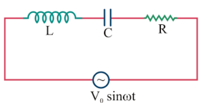
As per the series connection we have the phasor diagram of the circuit is
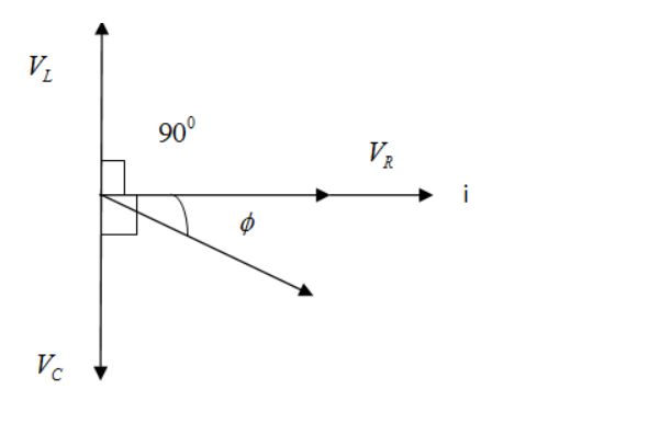
By using the phasor diagram we have;
Voltage across Resistor is VR , Voltage across capacitor is VCand Voltage across inductor is VL.
We have drawn the phasor diagram keeping VLgreater than VC, then VL- VC;
Total voltage across the circuit is;
⇒V=VR2+(VL−VC)2 .................1
Total current through the circuit is i
VR= i R , VC= i XC , VL= i XL ................2
We can replace the voltages in equation 1 by the values given in equation 2
⇒V=(iR)2+((iXL)2−(iXC)2
Impedance is given as;
⇒Z=i(iR)2+((iXL)2−(iXC)2
We will take out i common from the numerator and denominator;
⇒Z=ii(R)2+(XL)2−(XC)2(cancel i )
⇒Z=(R)2+(XL)2−(XC)2(Impedance of the series LCR circuit)
In the similar manner impedance or reactance of the LC,RC,RL circuit will be;
ZLR=R2+XL2 (Impedance of RL circuit)
ZRC=R2+XL2(Impedance of RC circuit)
ZLC=(XL−XC)2(Impedance of LC circuit)
Average power of the circuit is being calculated as;
Instantaneous values of the current and voltages are given by;
V=V0sinωt..............3 and I=I0sin(ωt+ϕ) .............4
Instantaneous power is given by;
P=VI
On multiplying the equation 3 and 4
We get;
⇒V0sinωt×I0sin(ωt+ϕ)................5
On further solving the equation 5 we get;
P=21V0I0cosϕ
Note:
Series LCR circuit has applications in radio and communication engineering. They can be used to select a certain narrow range of frequencies from the total spectrum of ambient radio waves. For example AM/FM radio along with analog turners use a RLC circuit to tune a radio frequency.