Solveeit Logo

Question

Question: If the switches \[{S_1}\],\[{S_2}\] and \[{S_3}\] in the figure are arranged such that current throu...
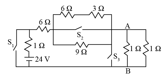
If the switches S1{S_1},S2{S_2} and S3{S_3} in the figure are arranged such that current through the battery is minimum, find the voltage across points A and B. (rounded off to nearest integer)

Explanation

Solution

The above problem can be resolved by undertaking the circuit analysis for the given circuit diagram and applying the concept of the series as well as the parallel connections of the resistors accordingly. In the first switch, the resistor is connected in series with the net resistance across the switch second. Similarly, the third switch is also in series with that of the second and the first.

Complete step by step answer:
As we know that when all the switches in an electrical circuit are opened, then the magnitude of the current through the battery will be minimal.
The current through the circuit is given as,
I=VRnetI = \dfrac{V}{{{R_{net}}}}
Here, V is the source of the voltage supply and its value is given as 24 V. And Rnet{R_{net}} is the net resistance across the terminals A and B.
As the 6  Ω6\;\Omega resistance and the 3  Ω3\;\Omega resistance above S2{S_2} is in series and together forms a parallel
connection with the 9  Ω9\;\Omega resistance. Then the net resistance at S2{S_2} is,

{R_1} = 6\;\Omega + 3\;\Omega \\\ {R_1} = 9\;\Omega \end{array}$$ Further solving as, $$\begin{array}{l} \dfrac{1}{{{R_2}}} = \dfrac{1}{{9\;\Omega }} + \dfrac{1}{{9\;\Omega }}\\\ {R_2} = \dfrac{9}{2}\;\Omega \end{array}$$ Similarly the net resistance across the switch $${S_3}$$ is, $$\begin{array}{c} \dfrac{1}{{{R_3}}} = \dfrac{1}{{1\;\Omega }} + \dfrac{1}{{1\;\Omega }}\\\ {R_3} = \dfrac{1}{2}\;\Omega \end{array}$$ The net resistance across the terminal A B is, $$\begin{array}{l} {R_{net}} = 1\;\Omega + 6\;\Omega + \dfrac{9}{2}\;\Omega + \dfrac{1}{2}\;\Omega \\\ {R_{net}} = 12\;\Omega \end{array}$$ The current through the circuit is, $$\begin{array}{l} I = \dfrac{V}{{{R_{net}}}}\\\ I = \dfrac{{24\;{\rm{V}}}}{{12\;\Omega }}\\\ I = 2\;{\rm{A}} \end{array}$$ Now, the voltage across the AB is, $$\begin{array}{l} {V_{AB}} = I \times {R_3}\\\ {V_{AB}} = 2\;{\rm{A}} \times \dfrac{1}{2}\;\Omega \\\ {V_{AB}} = 1\;{\rm{V}} \end{array}$$ Therefore, the voltage across the terminal AB is 1 volts. **Note:** Try to understand the concept of the series and the parallel connection of the resistors. The given problem needs to be applied to the accurate analysis of the circuit. Moreover, the concept of Ohm's Law to identify the magnitude of current and the voltage supply also need to be remembered.