Question
Question: If the power factor in a circuit is unity, then the impedance of the circuit is A. Inductive B. ...
If the power factor in a circuit is unity, then the impedance of the circuit is
A. Inductive
B. Capacitive
C. Partially inductive and partially capacitive
D. Resistive
Solution
It is important to know the definition of power factor for solving this question. The power factor is defined as the ratio of the real power absorbed by the load to the apparent power flowing in the circuit. It is a dimensionless number ranging from -1 to +1.
Complete step by step answer:
Consider the following LRC circuit connected to an AC source of voltage V=V0sinωt where ω is the angular frequency, ω=2πf:
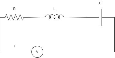
The impedance, Z is defined as the resistance offered to the flow of alternating current I through the entire circuit. Here, in the figure, the impedance Z is the vector sum of the reactances of the individual resistance, inductor, and the capacitor.
Capacitive reactance, Xc=ωC1
Inductive reactance, XL=ωL
Resistance is R.
Impedance, Z=R+(XL−XC)
These quantities cannot be added in a scalar manner since they have different phases. We have to add these values through vector addition by drawing the impedance triangle with ϕ as the phase angle.
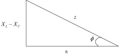
Thus, we can see that the Z is the vector sum of the reactance and the resistance as the triangle.
Z2=R2+(XL−XC)2
Here, the value of cosϕ is called the power factor, which gives the ratio of the real power that the load absorbs and the apparent power that the circuit absorbs.
Power factor = Real power / Apparent power
Power factor = I2ZI2R
Therefore, from the figure, we can write that, Power factor = ZR=cosϕ
For the power factor to be one, cosϕ=1
where, R=Z
Substituting in the impedance equation, we get –
Z2=R2+(XL−XC)2 ⇒R2=R2+(XL−XC)2 ⇒(XL−XC)2=0 ∴XL=XC
Here, we see that inductive and capacitive reactance is equal and thus, they cancel out each other. When they cancel out, only the resistance stands out.
Thus, the circuit where only resistance acts is called a resistive circuit. Hence, the correct option is Option D.
Note:
Some students may get confused as to why we have taken (XL−XC) and not (XC−XL). This arises from the fact that in this problem, the circuit is assumed generally, to be inductive. However, in the problem, if we have a capacitive circuit, we should consider the expression (XC−XL).