Question
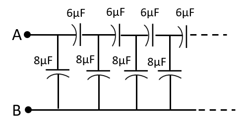
Question: (i) Find the equivalent capacitance of the infinite ladder shown in the figure between the terminals...
(i) Find the equivalent capacitance of the infinite ladder shown in the figure between the terminals A and B. (ii) If now each capacitor is replaced by a capacitor which is double in capacitance, then reevaluate the question.
Solution
For both cases, assume that a capacitor similar to the equivalent capacitance is connected across the second parallel branch of the circuit, since the equivalent capacitance between A and B remains unchanged from such an assumption. Then arrive at a quadratic equation for the equivalent capacitance and solve it. Eliminate the negative solution since capacitance cannot have a negative value to arrive at a positive value for the equivalent capacitance, which is what is required.
Formula used:
Cseries=C1+C2C1×C2
Cparallel=C1+C+2
Complete step-by-step answer:
(i)Let us assume that the equivalent capacitance between A and B of the infinite ladder shown is C.
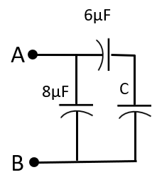
Assuming that a capacitance equivalent to C is connected in the circuit as shown in the figure below. Since it is one of the parallel branches across A and B, the equivalent capacitance between A and B still remains unchanged.
We now obtain an expression for the equivalent capacitance, say Ceq across A and B from the circuit shown in the above figure.
Since the capacitances 6μF andC are connected in series to each other, the cumulative capacitance, say C′ of the two will be:
C′=C1+C2C1×C2=6+C6×C=6+C6C
Now, the 8μF capacitance is parallel to C′. Therefore, the equivalent capacitance Ceq between A and B will be:
Ceq=8+C′=8+6+C6C=6+C8(6+C)+6C=6+C48+14C
But we’ve established that Ceq=C, therefore, the above equation becomes:
C=6+C48+14C
⇒C(6+C)=48+14C
⇒C2+6C–14C−48=0
⇒C2−8C−48=0
⇒C2−12C+4C−48=0
⇒C(C−12)+4(C−12)=0
⇒(C+4)(C−12)=0
⇒C=−4μF or C=12μF
SinceC cannot be negative, the appropriate choice would be C=12μF
Therefore, the equivalent capacitance between terminals A and B will be 12μF.
(ii) Given that each capacitor is replaced by a capacitor which is double in capacitance, as shown in the figure below.
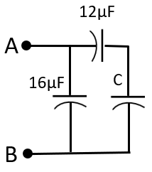
Following the same procedure as before, we get that the equivalent capacitance between A and B will be:
C′eq=12+C12×C+16=12+C12C+16(12+C)=12+C12C+192+16C
Plugging in Cprimeeq=C, the above equation becomes:
C=12+C28C+192
⇒C(12+C)=28C+192
⇒C2+12C−28C−192=0
⇒C2−16C−192=0
⇒C2−24C+8C−192=0
⇒C(C−24)+8(C−24)=0
⇒(C+8)(C−24)=0
⇒C=−8μF or C=24μF
SinceC cannot be negative, the appropriate choice would be C=24μF
Therefore, when the capacitances are doubled the equivalent capacitance between terminals A and B will be 24μF, which is twice the equivalent capacitance between them from the previous case.
Note: Remember that for capacitors in parallel, the net capacitance is the additive sum of individual capacitances, whereas for capacitors in parallel, the reciprocal of the net capacitance is the sum of the reciprocals of individual capacitances. The largest effective capacitance is obtained by connecting the capacitors in parallel, whereas the smallest effective capacitance is obtained by connecting the capacitors in series.
Do not get this confused with resistors, where for resistors in parallel, the reciprocal of the net resistance is the sum of the reciprocals of individual resistances resulting in the smallest effective resistance, whereas for resistors is series, the net resistance is the additive sum of individual resistances, resulting in the largest effective resistance.