Question
Question: How will you obtain OR, AND gates from the NAND and NOR gates? Write symbols, Boolean formula and tr...
How will you obtain OR, AND gates from the NAND and NOR gates? Write symbols, Boolean formula and truth table.
Solution
These are an electronic circuit. This electronic circuit performs a logic function. We can express its function and characteristics by using the Boolean equation. NAND & NOR gates not version of AND & OR gate. You will not find abbreviations of NAND & OR. It is not an acronym. Basically it means that it is a combination of AND and NOT & OR and NOT then we made shortcuts as NAND and NOR respectively.
Complete step-by-step answer:
We all know what logic is. Here is little additional. We have to identify which logic gate we want to use according to our requirement.
Truth table of AND-
| INPUT 1 | INPUT 2 | OUTPUT |
|---|---|---|
| A | B | Y=A.B |
| 0 | 0 | 0 |
| 0 | 1 | 0 |
| 1 | 0 | 0 |
| 1 | 1 | 1 |
Truth table of NAND-
| INPUT 1 | INPUT 2 | OUTPUT |
|---|---|---|
| A | B | Y=A.B |
| 0 | 0 | 1 |
| 0 | 1 | 1 |
| 1 | 0 | 1 |
| 1 | 1 | 0 |
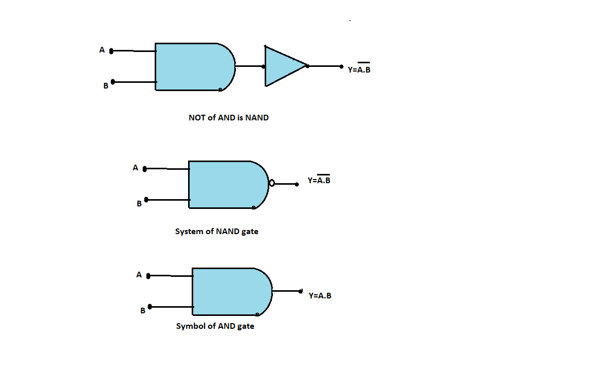
NAND and AND gate are one of the types of logic gates. NAND is followed by NOT gate. It means that when NOT is connected before AND gate. NAND gate is derived from NOT and AND.
NAND and AND gate have two inputs and one output. Logically NAND is a complement of AND gate. Any input may have low value or high value. When any of NAND gate’s inputs is LOW it produces HIGH output and it produces LOW output only when all of it is high, as you can see in above truth table. In the case of an AND gate it generates high output only when all of its inputs are high else output remains LOW. ‘.’ sign represents AND operation.
Like this you can extract AND from NAND.
Symbol of NAND and AND:
Truth table of OR-
| INPUT 1 | INPUT 2 | OUTPUT |
|---|---|---|
| A | B | Y=A+B |
| 0 | 0 | 0 |
| 0 | 1 | 0 |
| 1 | 0 | 0 |
| 1 | 1 | 1 |
Truth table of NOR-
| INPUT 1 | INPUT 2 | OUTPUT |
|---|---|---|
| A | B | Y=A+B |
| 0 | 0 | 1 |
| 0 | 1 | 0 |
| 1 | 0 | 0 |
| 1 | 1 | 0 |
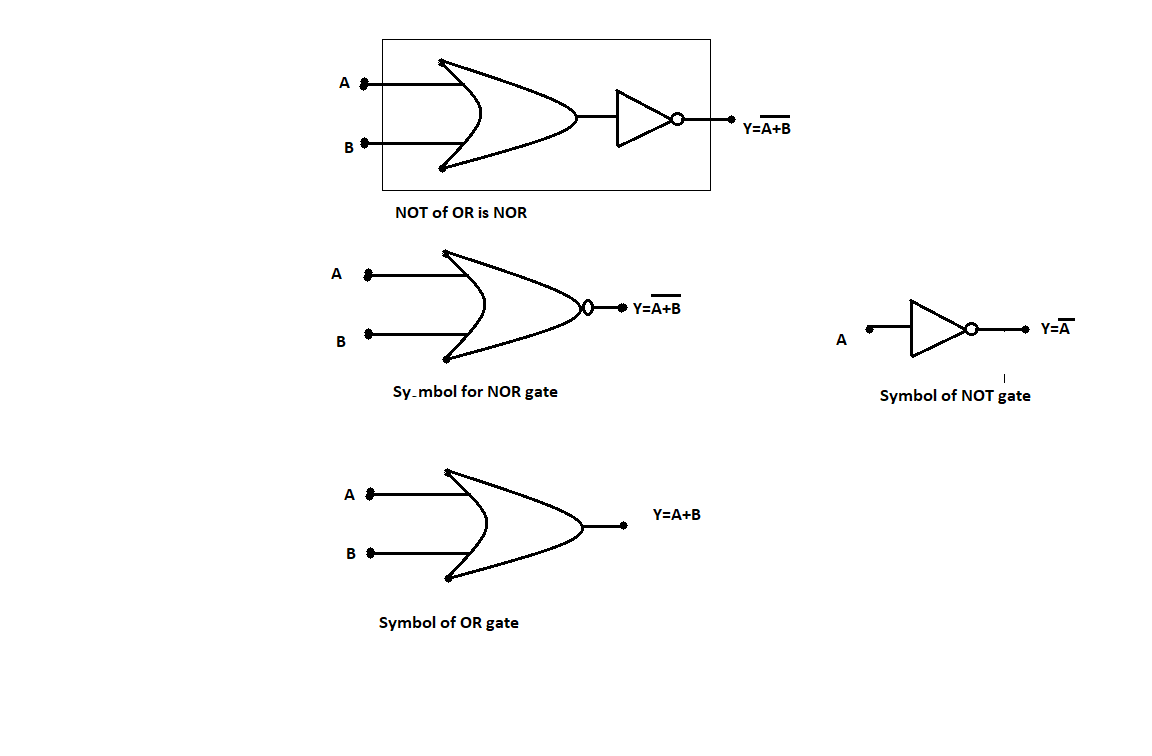
NOR and OR gates are one of the types of logic gates. NOR is followed by NOT gate. It means that when NOT is connected before OR gate. NOR gate is derived from NOT and OR.
NOR and OR gates have two inputs and one output. Logically NOR is a complement of OR gate. Any input may have low value or high value. When any of NOR gate’s inputs is HIGH it produces LOW output and it produces HIGH output only when all of it is LOW, as you can see in above truth table. In the case of an OR gate it generates LOW output only when all of its inputs are LOW else output remains HIGH. ‘+’ Sign represents OR operation.
Like this you can extract OR from NOR.
Symbol of NOR and OR:
Note: Basically when NOT gate is connected to AND and OR we get NOR and NAND gate. Here low value tends to 0 and high value tends to 1. Logic gate uses only two values which are 0 and 1. You can express and show output from input by using 0 and 1 as NAND’s, NOR’s, AND’s & OR’s input. These logic gates operate on discrete voltage levels.