Question
Question: How is the moving coil galvanometer converted to an ammeter and voltmeter?...
How is the moving coil galvanometer converted to an ammeter and voltmeter?
Solution
We need to find how the three electrical measuring devices – galvanometer, ammeter and the voltmeter are made to answer this question. Basically, the ammeter and the voltmeter are some variation of the galvanometer.
Complete answer:
An ammeter and voltmeter are devices which are used in electrical circuits to measure the values of current and voltage across respectively. These devices are modified versions of a galvanometer. A galvanometer is a device which is used to detect the presence of electric current in a circuit. We can use the galvanometer in different arrangements to make it either an ammeter or a voltmeter.
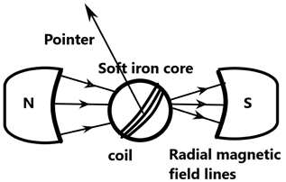
The galvanometer consists of a coil of ‘N’ turns with a soft iron core, which is free to rotate about a free axis. The cylindrical iron core with the coil is kept between the two poles with a bar magnet which due to its shape provides a sharp and radial magnetic in the coil. When current flows through the coil a torque is formed in the core which rotates the system which is calibrated and marked as measurements. The angle of deflection on the scale is given as –
ϕ=(kNAB)I
Where, k is the torsional constant of the spring that provides a counter torque to the coil to give a steady deflection, I is the current, A is the area of the core and B is the magnetic field. The quantity in the brackets is the torque in the system.
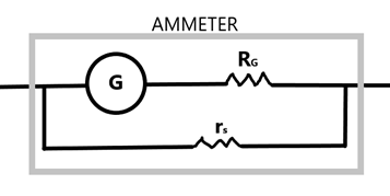
Ammeter: It is the device which has a small resistance parallel to the galvanometer coil. As a result, the current passes through this resistance making the galvanometer give a precise value on the current without over deflection. This is why ammeter is connected in series with the circuit.
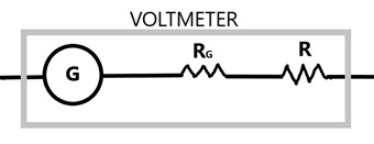
Voltmeter: It is the device which has a very high resistance series with the moving coil galvanometer. This helps the current to flow through the circuit which is parallel to the voltmeter as the voltage drop across this device itself will not be accounted for.
This is the required solution.
Note:
The ammeter and the voltmeter are devices which are used in measuring the circuit parameters. The resistance due to their internal design cannot be tolerated as it will result in wrong observations, which is why shunt resistances are used properly.