Question
Question: How does this allow us to measure the potential difference across a diode? An experiment involves ...
How does this allow us to measure the potential difference across a diode?
An experiment involves measuring the potential difference across a diode when it just begins to conduct. Which of the following circuits would allow this measurement to be made?
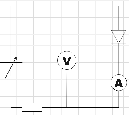
A.
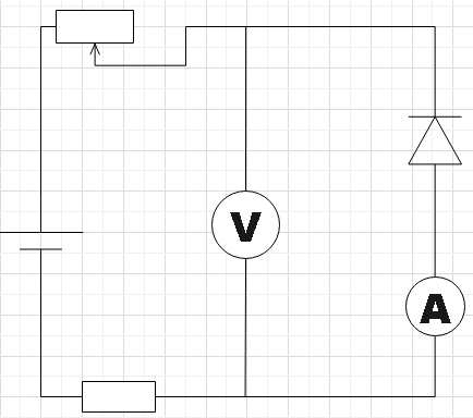
B.
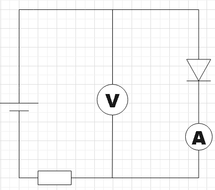
C.
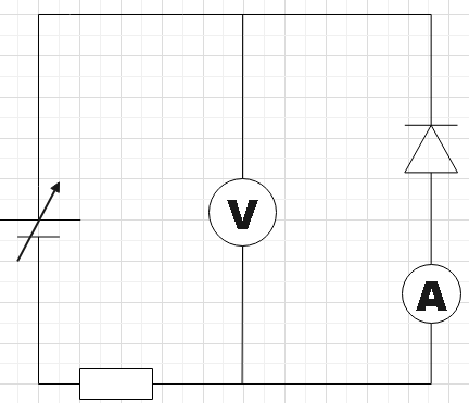
D.
Solution
As a very first step, you could have a close look at the given circuits and then understand the connections properly and then also recall the working of a pn junction diode. You also have ammeters in every circuit. So, you would be also able to measure the current in the circuit by using this ammeter.
Complete answer:
In the question, we are given four circuits set up for the purpose measuring the potential difference across the diodes in them. We are supposed to find which of the given circuits will correctly find the potential difference.
In circuit A we see that the diode is forward biased, that is, the positive of the voltage source is connected to the p-side of the diode and n-side to its negative terminal. If we increase the voltage of the source slowly by setting it initially to zero, the ammeter will show a small current and simultaneously you could also measure the potential difference across the diode in the voltmeter. You could follow the same steps for circuit D. But the voltmeter will be measuring the reverse bias voltage there.
Therefore, we found circuits A and D to be able to measure the potential difference across the diode.
Note:
One should be careful while doing the experiment. For circuit D, if you keep increasing the voltage of the source, chances are there for the diode getting damaged. Due to the fact that the marginal impedance of the diode that is in conduction mode remains less than the source impedance of supply voltage, the voltage measured would remain∼0.6V.