Question
Question: Given below is the circuit diagram of an AM demodulator. For good demodulation of AM signal of carri...
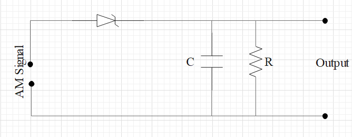
Given below is the circuit diagram of an AM demodulator. For good demodulation of AM signal of carrier frequency f, the value of RC should be
a)RC=f1
b)RC<f1
c)RC≥f1
d)RC>>f1
Solution
In a demodulator high frequency wave is filtered to get desired signal. For this a capacitance is used in parallel which helps in filtering the high frequency component of the imported modulated wave. Therefore, reactance of C should be smaller than the resistance. Using this result, find the relation between resistance, capacitance and frequency of the demodulator.
Formula used:
Reactance of a capacitor: ωC1, where ω is the angular velocity and C is the capacitance.
ω=2πf, where ω is the angular velocity and f is the frequency.
Complete step by step answer:
Reactance of a capacitor is given by: ωC1
Where, ω=2πf
Since, reactance of a capacitor should be smaller than the resistance.
So, we can say that:
\dfrac{1}{\omega C} << R \\\
⟹2πfC1<<R
⟹2πf1<<RC
Since 2π1 is a constant value, we can say:
f1<<RC
Therefore, RC>>f1.
So, the correct answer is “Option D”.
Note:
Modulation is the process of converting data into radio waves by adding information to an electronic or optical carrier signal. Demodulation as the name suggests is the reverse process of modulation. The process of recovering audio frequency signals from the modulated carrier waves is called detection or demodulation.