Question
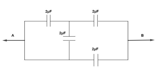
Question: Four capacitors are connected in a circuit as shown in figure. The effective capacitance is \(\mu F\...
Four capacitors are connected in a circuit as shown in figure. The effective capacitance is μF be points A and B will be
A. 310μF
B. 4μF
C. 5μF
D. 18μF
Solution
Whenever a complicated circuit is given as we have been asked to find out the result capacitance or resistance of the first step, we need to simplify the circuit in such a way that we can solve it in an easy manner. If possible, check if the circuit is making a bridge or not and if no bridge is found then try to solve the given resistance separately or in pairs.
Complete step by step answer:
The circuit can be rearranged as
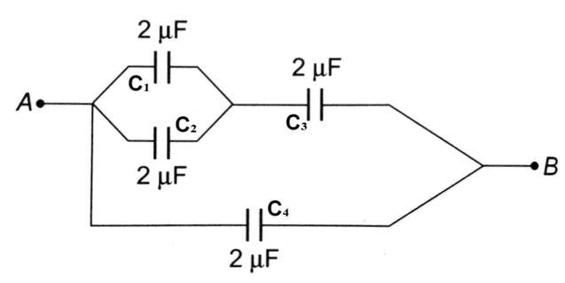
C1=C2=C3=C4=2μF
For parallel combination,
Cp=C1+C2
⇒Cp=4μF
For series connection,
Cnet=Cp+C3Cp×C3
Substitute the values for cp and c3 in the above equation
Cnet=4+24×2
⇒Cnet=68μF
Therefore,
Cnet=68μF
Now to find net total capacitance between AB,
Ctotal=Cnet+C4
⇒Ctotal=68μF+2μF
∴Ctotal=310μF
Additional information: A capacitor is a device which is used to store charge. Amount of charge ‘Q’ stored by the capacitor depends on voltage applied and size of capacitor. Capacitor consists of two similar conducting plates placed in front of each other where one plate is connected to the positive terminal while the other plate is connected to the negative terminal. In this, electric charge stored between plates of capacitor which is directly proportional to potential difference between plates, i.e.,
Q=CV
Where, C= Capacitance of capacitor, V=potential difference between the plates.
In a capacitor, energy is stored in the form of an electric field, in the space between the plates.
Note: The formula for capacitance in series is the same as that of resistance in parallel and the formula for capacitance in parallel is the same as that of the formula for resistance in series. Both the capacitor and resistor have their formula opposite in series as well as in parallel connection.