Question
Question: For the transistor circuit shown in figure, if \[\beta = 100\], voltage drop across emitter and base...
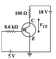
For the transistor circuit shown in figure, if β=100, voltage drop across emitter and base is 0.7V, then the value of VCE will be
Solution
Use KVL in the first loop to determine the base current. We know the amplification factor is the ratio of collector current to base current. Calculate the collector current using the given amplification factor. Then use KVL in the second loop to express the voltage drop across collector and emitter.
Formula used:
According to Ohm’s law,
V=IR
βAC=IBIC
Here, IC is the collector current and βAC s the AC current gain.
Complete step by step answer:
We can find the base current in the above transistor circuit by applying KVL in the first loop containing 5V supply, 8kΩ resistance as follows,
5−8.6IB−VBE=0
Here, VBE is the voltage drop across base and emitter and IB is the base current.
We substitute 0.7 V for VBE in the above equation.
5−8.6IB−0.7=0
⇒IB=8.65−0.7
⇒IB=0.5mA
We know the relation,
βAC=IBIC
⇒IC=βACIB
Here, IC is the collector current and βAC s the AC current gain.
We substitute 100 for βAC and 0.5 mA for IB in the above equation.
IC=(100)(0.5mA)
⇒IC=50mA
Now, to determine the voltage drop across collector-emitter, we apply KVL is the second loop as follows,
VCC−ICR−VCE=0
Here, VCC is the collector voltage and VCE is the voltage across the collector-emitter.
We substitute 18 V for VCC, 50mA for IC and 100Ω for R in the above equation.
18−(50×10−3A)(100Ω)−VCE=0
⇒VCE=13V
Therefore, the voltage drop across the collector-emitter is 13 V.
Note:
We know KVL states that the voltage in the complete loop is the sum of voltage drop across each component. IF there is addition of voltage in the loop, then it should be taken as positive and if there is drop in the voltage then it should be taken as negative. In the above solution, we have taken the collector voltage positive because it gets added in the voltage from the second loop.