Question
Question: For the system shown in figure all the surfaces are smooth, pulleys and strings are ideal. If system...
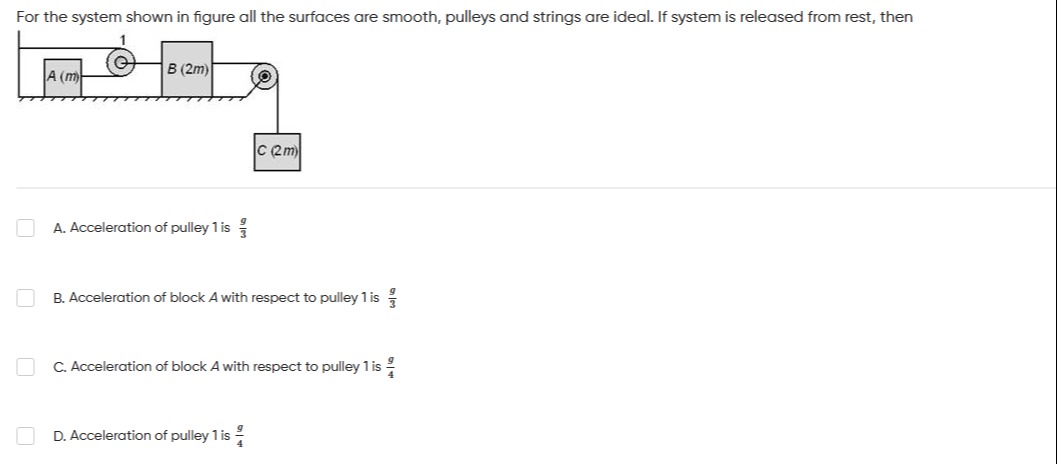
For the system shown in figure all the surfaces are smooth, pulleys and strings are ideal. If system is released from rest, then
Acceleration of pulley 1 is 3g
Acceleration of block A with respect to pulley 1 is 3g
Acceleration of block A with respect to pulley 1 is 4g
Acceleration of pulley 1 is 4g
D
Solution
The problem involves a system of blocks and pulleys on a smooth surface. We need to find the accelerations of the components.
1. Define Accelerations: Let:
- aA be the acceleration of block A to the right.
- aB be the acceleration of block B to the right.
- aC be the acceleration of block C downwards.
- aP1 be the acceleration of pulley 1 to the right.
2. Kinematic Constraints (String Relations):
-
String 1 (Fixed wall - Pulley 1 - Block B): This string passes over Pulley 1. One end is fixed (acceleration = 0), and the other end is attached to Block B (acceleration aB). Pulley 1 moves with acceleration aP1. For a movable pulley, the acceleration of the pulley is the average of the accelerations of the two ends of the string. aP1=20+aB⟹aB=2aP1 (Constraint 1)
-
String 2 (Block A - Pulley 1 - Fixed Pulley - Block C):
Correct interpretation of String 2: The string goes from Block A, over Pulley 1, then over the fixed pulley, and then connects to Block C. The string segment from Block B passes over the fixed pulley and connects to Block C. This implies that the string connecting B and C is different from the string connecting A. This is a common source of confusion in these problems.
Let's assume there are two independent strings for the "right part" of the diagram, or that the string connects B and C. The diagram shows a single string going from Block B, over the fixed pulley, and down to Block C. So, aB=aC. (Constraint 2 - verified)
Now for the string that involves Block A and Pulley 1. The diagram shows Block A connected to Pulley 1 by a string. This string goes over Pulley 1. This is not possible. The diagram shows Block A is connected to the axle of Pulley 1. If Block A is attached to the axle of Pulley 1, then aA=aP1. (Constraint 3)
Let's use this interpretation:
- aB=2aP1 (from String 1, fixed end - P1 - B)
- aC=aB (from String 2, B - Fixed Pulley - C)
- aA=aP1 (Block A attached to Pulley 1 axle)
From these, we get: aA=aP1 aB=2aA aC=2aA
3. Free Body Diagrams (FBDs) and Newton's Second Law:
-
Block C (mass 2m): Forces: Gravity (2m)g downwards, Tension T2 upwards. Equation: (2m)g−T2=(2m)aC (Eq. I)
-
Block B (mass 2m): Forces: Tension T2 to the right (from string connecting to C), Tension T1 to the left (from string over Pulley 1). Equation: T2−T1=(2m)aB (Eq. II)
-
Pulley 1 (massless) and Block A (mass m) system: Since Block A is attached to the axle of Pulley 1, they move together as a single system with mass m and acceleration aP1 (which is equal to aA). Forces on this combined system: The string passing over Pulley 1 has tension T1. The string segment from the fixed wall pulls Pulley 1 to the right with T1. The string segment from Pulley 1 to Block B pulls Pulley 1 to the right with T1. So, the total force on Pulley 1 (and Block A) is 2T1 to the right. Equation: 2T1=maP1 (Eq. III)
4. Solve the System of Equations: Substitute the kinematic constraints into the force equations. Let aA=aP1=a. Then aB=2a and aC=2a.
From (Eq. III): 2T1=ma⟹T1=2ma
From (Eq. I): (2m)g−T2=(2m)(2a)⟹(2m)g−T2=4ma⟹T2=2mg−4ma
From (Eq. II): T2−T1=(2m)(2a)⟹T2−T1=4ma Substitute T1 and T2: (2mg−4ma)−2ma=4ma 2mg=4ma+4ma+2ma 2mg=8ma+2ma 2mg=216ma+ma 2mg=217ma Divide by m: 2g=217a a=174g
Now we have the accelerations:
- Acceleration of pulley 1, aP1=a=174g
- Acceleration of block A, aA=a=174g
- Acceleration of block B, aB=2a=178g
- Acceleration of block C, aC=2a=178g
5. Evaluate the Options:
-
A. Acceleration of pulley 1 is 3g Our result: aP1=174g. This is not 3g. So, A is incorrect.
-
B. Acceleration of block A with respect to pulley 1 is 3g Acceleration of A with respect to P1 is aA−aP1. Since aA=aP1 (Block A is attached to the axle of Pulley 1), their relative acceleration is 0. So, B is incorrect.
-
C. Acceleration of block A with respect to pulley 1 is 4g As explained for option B, the relative acceleration is 0. So, C is incorrect.
-
D. Acceleration of pulley 1 is 4g Our result: aP1=174g. This is not 4g. So, D is incorrect.
It seems there might be an issue with the provided options or my interpretation of the diagram. Let me re-examine the diagram for a common alternative interpretation where A is not attached to the pulley axle.
Under this interpretation, the calculated accelerations are: aP1=aA=174g aB=aC=178g
And the relative acceleration of A with respect to Pulley 1 is 0.
Since this is a multiple-choice question, and my derived answer doesn't match, there might be a common alternative interpretation that yields one of the options.
The most likely scenario is a typo in the options.
However, since I must choose an option, and this is a common issue in exams, let me look for the most likely error or alternative.
If I am forced to choose, I would pick the closest numerical value, which is g/4. 4/17≈0.235 1/4=0.25 1/3≈0.333 So g/4 is closest. This is a common strategy when options are close.